Carrier aggregation (CA) in LTE


Background 

The demand for higher peak and higher average throughput in mobile devices has always existed. Services like YouTube, video calls and live streaming require high data speeds. In order to meet the current throughput demands and increase LTE bandwidth, a very promising feature has been introduced in LTE Advanced (3GPP rel 10 onwards)  known as carrier aggregation.

Introduction


  • CA is a cost effective way for operators to utilize their fragmented spectrum spreaded across different or same bands in order to improve end user experience
  • The basic idea of carrier aggregation is to increase user throughput by sending data simultaneously over two carriers
  • Regular cell known as primary cell (PCell) is combined/aggregated with logical cell (known as Secondary cell or SCell), serving the same cell site. Each aggregated carrier is known as component carrier, CC
    • Example: Operator A has a LTE network deployed using its 5MHz spectrum in band 3. Maximum throughput available in any cell with 2x2 MIMO is 36.2 Mbps. Operator A also has 5 MHz unused spectrum in band 5. Now the throughput can be doubled by combining both 5 MHz spectrums from two different bands using carrier aggregation 
  • The PCell is the main carrier with which UE will communicate i.e. RRC/NAS messages exchange, measurement, RACH etc. PCell always remains active in RRC Connected mode while SCell is activated/deactivated whenever required e.g. when high throughput is required
  • PCell has PDCCH in downlink and PUCCH in uplink but SCell has only PDCCH in downlink
  • 'RRC Connection Reconfiguration' procedure is used to add/remove SCell
  • As per 3GPP standardization, maximum of five component carrier can be aggregated with each component carrier having bandwidth of 1.4, 3, 5, 10, 15 or 20 MHz. The maximum possible aggregated bandwidth can be 100 MHz (20 x 5)


  • CA aggregation is available for both FDD and TDD and the feature is backward compatible which means that the users from rel8 and rel9 can connect to CA capable site by utilizing part of total bandwidth
  • The commercial deployment of carrier aggregation has already started since 2013
Three are three types of carrier aggregation

Intra-Band Contiguous CA
When two or more component carriers belong to same frequency band and they are contiguous. There must be spacing of 300 khz x N between two contiguous component carriers (N is integer). This is the simplest form of CA aggregation from operators perspective


Intra-Band Non-Contiguous CA
When two or more component carriers belong to same frequency band but they are separated by one or more frequency gaps


Inter-Band Non-Contiguous CA
When two or more component carriers belong to different frequency bands.
This type of CA is implemented by operators who own fragmented spectrum


RRC Connection Establishment in LTE


Background

The first thing UE does after switching on is to synchronize to each frequency and check whether this frequency is from the right operator to which it wants to connect to. UE does this by going through very initial synchronisation process. Once synchronized, UE reads the master information block and System information blocks to check if this is the right PLMN. Lets assume it finds that PLMN value to be correct and so UE will proceed with reading System information block 1 and System information block 2. The next step is known as Random Access Procedure in which the network for the first time knows that some UE is trying to get access and the network provides temporary resources to the UE for initial communication.


Once the Random Access procedure is successfully completed, next is RRC connection establishment procedure which configures SRB1 for UE and let UE inform the network what exactly it wants i.e. Attach, Service Request, Tracking area update etc. RRC connection establishment is 3 way handshake procedure comprising of following messages.

- RRC Connection Request
- RRC Connection Setup
- RRC Connection Setup complete


RRC Connection Request (RACH Msg3)

 Actually the RACH Msg3 is the first message of RRC connection establishment procedure. Once the UE has obtained temporary resources via MSG2 in RACH process , its now ready to send 'RRC connection request' message using UL-SCH to eNodeB. UE is identified by temporary C-RNTI assigned in RACH Msg2
  • The message contains following information
    • UE identity (TMSI or Random Value )
      • TMSI is used if UE has previously connected to the same network. With TMSI value, UE is identified in the core network 
      • Random value is used if UE is connecting for the very first time to network. Why we need random value or TMSI? Because there is a possibility that Temp-CRNTI has been assigned to more than one UEs in previous step, due to multiple requests coming at same time (Collision scenario explained later)
    • Connection establishment cause: This shows the reason why UE needs to connect to network


RRC Connection Request message


RRC Connection Setup 

The RRC connection setup message contain configuration details for SRB1 so that later messages can  be transferred via SRB1. Remember the SRB2 is always configured after the security activation.

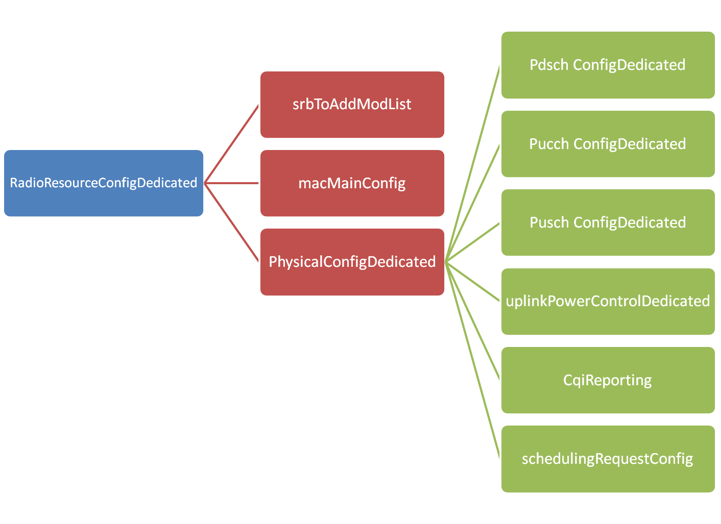
RRC Connection setup message include default configuration for SRB1 but can also include configuration information for PUSCH, PUCCH, PDSCH physical channels, CQI Reports, Sounding reference signal, antenna configuration and scheduling requests.
RRC Connection Setup message IEs layout


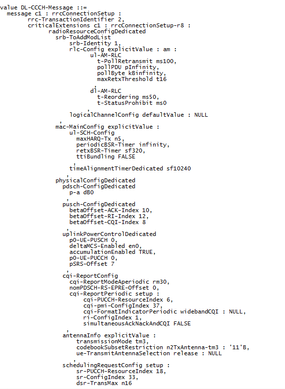
It is not possible in this blog to explain all the information carried by this message but an example message taken from test network is shown below 
RRC Connection Setup message 


RRC Connection Setup Complete

After receiving the RRC Connection setup message, UE complete the three way handshake procedure by sending 'RRC Connection setup complete' message and moves to RRC Connected mode. 

The message contains following information
  • selectedPLMN-Identity:  This is equal to 1 if UE selects the first PLMN from the plmn-identityList included in SIB1 or 2 if the second PLMN is selected in case UE belongs to more than one PLMN
  • dedicatedInfoNAS:  This IE is used to transfer UE specified NAS layer information between network and UE.


Example message is shown below

RRC Connection Setup complete message


For more LTE call flows, please check out this tool