Transport Block Size, Throughput and Code rate

Since the size of transport block is not fixed, often a question comes to mind as to how transport block size is calculated in LTE.

Back Ground
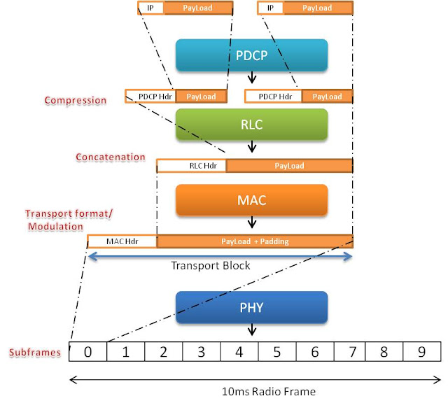
If we only consider "Uplink direction" and we assume that the UE is already attached to the network, then data is first received by PDCP (Packet data compression protocol) layer. This layer performs compression and ciphering / integrity if applicable. This layer will pass on the data to the next layer i.e. RLC Layer which will concatenate it to one RLC PDU.

RLC layer will concatenate or segment the data coming from PDCP layer into correct block size and forward it to the MAC layer with its own header. Now MAC layer selects the modulation and coding scheme configures the physical layer. The data is now in the shape of transport block size and needed to be transmitted in 1ms subframe.


Transport Block size

Now how much bits are transferred in this 1ms transport block size? 
It depends on the MCS (modulation and coding scheme) and the number of resource blocks assigned to the UE. We have to refer to the Table 7.1.7.1-1 and Table 7.1.7.2.1-1 from 3GPP 36.213

Lets assume that eNB assigns MCS index 20 and 2 resource blocks (RBs) on the basis of CQI and other information for downlink transmission on PDSCH. Now the value of TBS index is 18 as seen in Table 7.1.7.1-1


After knowing the value of TBS index we need to refer to the Table 7.1.7.2.1-1 to find the accurate size of transport block (Only portion of the table is shown here while for the complete range of values refer to 3gpp document 36.213 http://www.quintillion.co.jp/3GPP/Specs/36213-920.pdf)


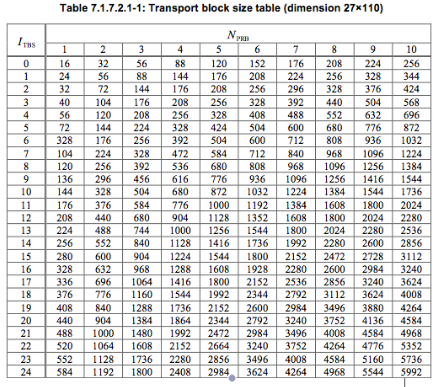
Now from the Table 7.1.7.2.1-1 the value of Transport block size is 776 bits for ITBS = 18 and NPRB=2

Throughput

Throughput is simply = Transport block size*(1000) = 776 *1000 = 776000 bits / seconds = 0.77 mbps (Assuming MIMO not used)

Please check this Throughput Calculator which takes MCS values and number of resource blocks as input to calculate the downlink throughput


Code Rate

In simple words, code rate can be defined as how effectively data can be transmitted in 1ms transport block or in other words, it is the ratio of actual amount of bits transmitted to the maximum amount of bits that could be transmitted in one transport block

code rate = (TBS + CRC) / (RE x Bits per RE)

where
TBS = Transport block size as we calculated from Table 7.1.7.2.1-1
CRC = Cyclic redundancy check i.e. Number of bits appended for error detection
RE = Resource elements assigned to PDSCH or PUSCH
Bits per RE = Modulation scheme used


While we know the values of TBS, CRC and bits per RE (modulation order), it is not easy to calculate the exact amount of RE used for PDSCH or PUSCH since some of the REs are also used by control channels like PDCCH, PHICH etc

In our case, lets assume that 10% of RE's are assigned for control channels then

TBS = 776
CRC = 24
RE = 2 (RB) x 12 (subcarriers) x 7 (assuming 7 ofdm symbols) x 2 (slots per subframe) x 0.9 (10% assumption as above) = 302 REs
Bits per RE = 6 (Modulation order from table 7.1.7.1-1)

So

code rate = (776 + 24) / (302 * 6 ) = 0.4


AKA Digest authentication scheme for VoLTE (IMS)

When a VoLTE client needs to connect to IMS network, it has to authenticate the network while network also needs to make sure that only the correct user is registered to its network. AKA Digest is one of the scheme to authenticate VoLTE client to the IMS server


AKA

AKA stands for "Authentication and key agreement". This scheme comes from the legacy 3gpp networks and has been widely used in LTE, 3G, CDMA and WiMAX technologies. In this mechanism, a secret key is already known to both user device (USIM, iSIM) and authentication servers (HSS, HLR). 

The server will challenge the end user using AKA algorithms and shared key and sends RAND, AUTN values towards UE. UE will authenticate network and prepares result (RES for network to authenticate UE) with the help of shared key in UICC and parameters sent by Server.


HTTP Digest

Http Digest is the popular authentication scheme used for authenticating users to access web servers and other applications which requires security and data integrity. This scheme is much secure than the basic authentication as it applies hash function to the password before sending it [RFC2617]. 

HTTP Digest is username / password based authentication procedure. The authentication server provides one time created " nonce " value to the client. The client uses the nonce value and creates a secure response that contains  the password, username and other parameters to the server. The password which is known both to server and client, is always fixed


Now For IMS

Now since IMS is a part of 3GPP and on the contrary SIP signaling defines http digest for authentication [RFC3261]. Therefore in order to use 3GPP AKA with IMS, the parameters from AKA are mapped onto http digest [RFC3310]. In simple words the parameters / headers used to transport http digest information, will transport AKA information in identical format

With 3GPP AKA digest, the "nonce" now contains RAND, AUTN. The password now contains the one time RESPONSE generated by client with help of UICC (USIM, ISIM). Thus the method is even more secure. 


Authentication in IMS networks

  • VoLTE Client sends SIP register request to IMS Server. The user is not authenticated at this  point. The SIP register request contains IMS related identities (private identity, public identity, URI, etc)
  • The IMS server (S-CSCF) obtains authentication vector and SQN from HSS that contains a random challenge RAND, authentication token AUTN, expected authentication result XRES, a session key for integrity check IK, and a session key for encryption CK
  • The server creates an authentication request, which contains the random challenge RAND, and the network authenticator token AUTN
  • The authentication request is delivered to the client with "401 UNAUTHORIZED" message
  • The client verifies the AUTN with the ISIM. If the verification is successful, the network has been authenticated. The client then produces an authentication response RES, using the shared secret K and the random challenge RAND
3GPP AKA Operation in IMS


  • The authentication response RES is delivered to the server using new regiser sip message
  • The server compares the authentication response RES with the expected response. If the two match, the user has been successfully authenticated
  • Session keys IK and CK can be used for protecting further communications between the client and the server
  • Server sends "200 OK" message to inform the VoLTE client about successful registration


Android Operating System and Radio Interface Layer

When the mobile phone is switched on, in the first step Linux Kernel is loaded along with the drivers for modem and the first process called "init" is started. 'Init' will start initial dummy process named 'zygote' which helps in starting other services like audio manager, surface flinger, power manager, RIL Daemon (to be explained later), service manager, Telephony service etc 

All the smartphone applications communicate to external ports or environment via Application programming interface (API). For communication towards radio modem, Telephony framework (mentioned above) performs the role of APIs. It helps to access network related services by applications i.e. PDP connection establishment, SMS, MMS etc. Whenever these applications make any query, it is forwarded to Radio interface Layer (RIL) by telephony framework APIs. RIL is interface between telephony framework and radio hardware (modem)

RIL has two sub layers 

  • RIL Daemon: It communicates with Vendor RIL for call processing and other functions
  • Vendor RIL: It contains Library of functions and drivers to particular modem. It communicates with the radio hardware 


RIL Daemon is responsible for initializing Vendor RIL and forwards all requests from telephony framework to Vendor RIL. Vendor RIL communicates to modem protocol stacks via Hayes AT commands and forwards requests from modem to RIL Daemon or vice versa. Please see the figure above.

So here it is what happens:

  1. Android Mobile is switched on
  2. Linux Kernel is loaded
  3. Initial temporary process named zygote is started on initialization by Linux Kernel
  4. Zygote helps in quick start of other services including Android Telephony network and RIL Daemon (RILD)
  5. RILD initializes the vendor RIL for communication
  6. Vendor RIL initiates the radio modem
  7. Network attach procedure is started


System Information Block 1

After initial cell synchronisation and reading Master information block, UE will proceed to read system information blocks to obtain important cell access related parameters.

SIB1 broadcasts common information to all UEs in the cell related to cell access parameters and information related to scheduling of other SIBs. SIB1 is broadcasted in subframe # 5 in the SFN for which SFN mod 8 = 0. While the repeated copies are sent in subframe # 5 for which SFN mod 2 = 0 . Thus the new copy of SIB1 is transmitted every 80ms as shown below


The cell access related parameters are listed below

  • PLMN identity : Upto 6 PLMN identies can be specified
  • Tracking area code: Range from 0 to 65546
  • Cell Id: It contains eNB identity and has length of 28 bits
  • Cell barred: whether cell is barred or not
  • Intra Frequency cell reselection info: To select other cells when the target cell is barred
  • CSG indication: To indicate whether this cell is CSG cell or not. If it is CSG cell, then CSG identity stored in the UE should match with CSG id of the cell
Other information broadcasted by SIB 1 are 
  • q-RxLevMin: Minimum required level in the cell 
  • Band indicator: Cell frequency band indicator
  • scheduling information of other system information blocks
Complete SIB1 info is shown below (taken from UE logs). This SIB1 does not represent any real network


Load balancing in LTE Self-organizing networks (SON)

Load imbalance is one of the well known issues in communication networks. There is always a possibility that the heavily loaded cell is the neighbor of lightly loaded cell. In this case, load can be shared between these two neighbor cells. This usually require manual adjustment of the network parameters.

 In LTE network, the concept of self organizing networks is introduced where network parameters are adjusted automatically based on algorithm with the help of UE measurements. Load balancing (LB) at eNB is also introduced as one of the SON features.

The goal of the load balancing in LTE SON is to reduce cell congestion automatically by running SON algorithms at eNB. The benefits are listed below:

  • - The cell load is balanced 
  • - This will increase the system capacity by reducing the congestions in heavily loaded cells
  • - Auto optimization and management of network achieved 


The load balancing algorithm can include intra-frequency, inter-frequency or inter-RAT re selections/handovers as long as there is availability of target frequency layer

Policy charging and Rules Function (PCRF)

PCRF is an important entity in the LTE core network domain, initially introduced in 3gpp rel 5. It is mainly responsible for policy-making and control decisions. In simple words, if a user needs better quality of service (lets suppose in case of VoLTE ) then it is the responsibility of PCRF to initiate QoS with instructions from IMS. The functionality is listed below
  • Provide QoS information to packet gateway 
  • Dynamically manage and control data sessions. Example: For VoIP session, PCRF will initiate dedicated bearer dynamically
  • Enforce minimum QoS parameters
  • Determine charging policy for packets


Why TD-LTE ?

Operators are spending millions of dollars just on the license only. It is expected that TDD spectrum will be sold at lower price as compared to FDD spectrum and secondly the TDD spectrum is also available in many countries. So certainly there is emerging interest in TD-LTE. Some of the main advantages of TD-LTE over FDD-LTE are as follows

In FDD LTE (Frequency division duplex)

  • duplexing scheme requires paired spectrum which in other words means that the downlink and uplink transmission should be on different frequency spectrum
  • There is wastage of frequency resources in up-link if most UEs in the cells are using downlink spectrum most the time or vice versa (For example if most users in he cells are watching YouTube or downloading some files)
  • Since different range of frequencies are used in uplink and downlink, therefore channel characteristics are different in both directions. UE needs to report the downlink channel characteristics to the eNB on its uplink channels
  • Additional hardware required on UE and eNB side to separate uplink and downlink frequencies which adds extra cost to the terminals and base stations
Now in TD-LTE (Time division duplex) ? 

  • Paired spectrum is not required and both downlink / uplink communication occurs on single frequency channel
  • Channel characteristics are same for both uplink and downlink channels
  • Hardware cost is low, no need of diplexer in UE and eNB
  • Spectrum is efficiently utilized since UEs can use all the slots for downlink traffic if there is no uplink traffic

TD-LTE frame structure is shown in the figure below
Subframe 0 and 5 carries synchronization signals and system information blocks
Subframe 1 is special subframe that is used to carry information for switching between uplink and downlink for 10ms switching period
For 5 ms switching period both subframe 1 and 6 are used


ICIC and eICIC

Background

  • LTE is designed for frequency reuse 1 (To maximize spectrum efficiency), which means that all the neighbor cells are using same frequency channels and therefore there is no cell-planning to deal with the interference issues
  • There is a high probability that a resource block scheduled to cell edge user, is also being transmitted by neighbor cell, resulting in high interference, eventually low throughput or call drops (see figure) 
  • Traffic channel can sustain upto 10% of BLER in low SINR but control channels cannot. Neighbor interference can result in radio link failures at cell edge.
  • Heterogeneous networks require some sort of interference mitigation, since pico-cells/femto cells and macro-cells are overlapping in many scenarios


ICIC (Inter-cell interference coordination)

  • Inter-cell interference coordination is introduced in 3GPP release 8
  • ICIC is introduced to deal with interference issues at cell-edge
  • ICIC mitigates interference on traffic channels only
  • ICIC uses power and frequency domain to mitigate cell-edge interference from neighbor cells 
  • One scheme of ICIC is where neighbor eNBs use different sets of resource blocks through out the cell at given time i.e. no two neighbor eNBs will use same resource assignments for their UEs. This greatly improves cell-edge SINR. The disadvantage is decrease in throughput throughout the cell, since full resources blocks are not being utilized.
  • In the second scheme, all eNBs utilize complete range of resource blocks for centrally located users but for cell-edge users, no two neighbor eNBs uses the same set of resource blocks at give time
  • In the third scheme (probably the preferred scheme), all the neighbor eNBs use different power schemes across the spectrum while resource block assignment can be according to second scheme explained above. For example, eNB can use power boost for cell edge users with specific set of resources (not used by neighbors), while keeping low signal power for center users with availability of all resource blocks (see the figure)
  • X2 interface is used to share the information between the eNBs

eICIC (enhanced Inter-cell interference coordination)

  • eICIC introduced in 3GPP release 10
  • eICIC introduced to deal interference issues in Heterogeneous Networks (HetNet)
  • eICIC mitigates interference on traffic and control channels
  • eICIC uses power, frequency and also time domain to mitigate intra-frequency interference in heterogeneous networks
  • eICIC introduces concept of "Almost blank subframe" (ABS). ABS subframes do not send any traffic channels and are mostly control channel frames with very low power. If macro cell configure ABS subframes then UEs connected to pico/femto cells can send their data during such ABS frames and avoid interference from macro cell (see the figure)
  • ABS configuration is shared via OAM or x2 interface

Master Information Block (MIB) in LTE


The very first step for UE to gain initial access to the network after completing initial cell synchronization is to read the Master information block (MIB) on BCCH (Logical channel), BCH (Transport channel) and PBCH (Physical channel). Resource elements used by MIB are the first 4 OFDMA symbols of second slot of first subframe of a radio frame. On frequency domain it occupies 72 subcarriers. MIB carries very little but most important information for UE initial access. The content of MIB includes

·         Downlink channel bandwidth in term of resource blocks (RBs)
·         PHICH configuration (PHICH duration and PHICH resource)
·         System Frame Number

New MIB is broadcasted every radio frame for which SFN mod 4 = 0 (40ms repetition) while its copies are broadcasted in the middle 10ms radio frames as shown in the figure below


Why PHICH is carried by MIB? 
After decoding MIB, UE has to decode PDCCH to read other system information blocks (SIBs).  PDCCH, PHICH and PCFICH share the resources in the control region of a subframe. So to find the available resources for PDCCH, UE has to know the PHICH configuration only, as PCFICH resources are fixed and known

Semi persistent scheduling

Every VoIP packet is received / sent every 20ms when the user is talking whereas in silence period, discontinuous transmission (DTX) is used to reduce the transmission rate. Also, in order to sustain voice quality, silent insertion descriptor (SID) packet arrives every 160ms. The frequent arrival/transmission of VoIP packet means large control overhead for lower layers (L1/L2) in the radio protocol stack. To deal with this issue, semi persistent scheduling plays an important role.

Scheduling is a mechanism where UE requests eNB for the resource allocation during each transmission time interval (TTI). If UE has some data that it needs to transmit continuously, it will request eNB every TTI for the resource allocation. This scheduling type is dynamic scheduling. The advantage of dynamic scheduling is flexibility and diversity of resource allocation but as mentioned, this results in huge L1/L2 load which in turn means inefficient use of scarce radio resources.

In case of semi persistent scheduling, eNB can assign predefined chunk of radio resources for VoIP users with interval of 20ms. Therefore, UE is not required to request resources each TTI, saving control plan overhead. This scheduling is semi-persistent in the sense that eNB can change the resource allocation type or location if required for link adaptation or other factors.

Primary and secondary synchronization signals (PSS & SSS) in LTE


Cell synchronization is the very first step when UE wants to camp on any cell. From this, UE acquires physical cell id (PCI), time slot and frame synchronization, which will enable UE to read system information blocks from a particular network.

UE will tune it radio turn by turning to different frequency channels depending upon which bands it is 
supporting. Assuming that it is currently tuned to a specific band / channel, UE first finds the primary 
synchronization signal (PSS) which is located in the last OFDM symbol of first time slot of the first subframe (subframe 0) of radio frame as shown in figure (green squares). This enables UE to be synchronized on subframe level. The PSS is repeated in subframe 5 which means UE is synchronized on 5ms basis since each subframe is 1ms. From PSS, UE is also able to obtain physical layer identity (0 to 2).

In the next step UE finds the secondary synchronization signal (SSS). SSS symbols are also located in the same subframe of PSS but in the symbol before PSS as shown in the figure(yellow squares). From SSS, UE is able to obtain physical layer cell identity group number (0 to 167).

Using physical layer identity and cell identity group number, UE knows the PCI for this cell now. In LTE 504 physical layer cell identities (PCI) are allowed and are divided into unique 168 cell layer identity groups where each group consist of three physical layer identity. As mentioned earlier, UE detects physical layer identity from PSS and physical layer cell identity group from SSS. Assuming physical layer identity = 1 and cell identity group=2 then the PCI for given cell is

PCI = 3*(Physical layer cell identity group)+ physical layer identity = 3*2+1 = 7

Once UE knows the PCI for a given cell, it also knows the location of cell Reference signals as shown in figure (red and black squares). Reference signals are used in channel estimation, cell selection / reselection and handover procedures. 


LTE Resource Grid (Source: http://paul.wad.homepage.dk/LTE/lte_resource_grid.html)

After cell synchronization procedure, UE will proceed to read Master information and other System information blocks
Please see below sections
Master information block (MIB)
System information block 1 (SIB1)
System information block 2 (SIB2)


Robust Header Compression (RoHC)

For VoIP packets, the size of headers (IP/UDP/RTP) is usually larger than the data itself. Compressing these protocol headers over end to end (User to user) connection is not feasible since the headers play important role, but there is possibility to compress them over the air interface i.e. between UE and eNB/NB/BTS etc. Over the air interface, protocol headers do not play any role, so therefore there is considerable reduction in the data over head on radio interface. For IPv4, UDP and RTP, the amount of overhead due to headers is 40 bytes while RoHC can compress this to 2 or 3 bytes. RoHC is described in RFC 3095


In LTE, the role of Packet data convergence protocol layer (PDCP) is to implement RoHC as shown below (Only uplink traffic shown). 
RoHC is applied to user plane traffic only while this feature is transparent to control plane traffic.


Use of RoHC with conversational bearer (QCI 1) in LTE will result in efficient use of radio resources since it can reduce the user plane traffic by several bytes over air interface.

Automatic Neighbor Relation (ANR) in LTE

Manually adding neighbor cells in network is indeed a very hectic process and prone to errors as well. While  networks are becoming more and more complex, it is required to find an automatic and a more optimized way of adding neighbor cells.

ANR comes under the umbrella of Self Organizing Networks ( SON) features. ANR relies on UE to detect unknown cells and report them to eNB. There are two major types:

i) UE based ANR
ii) ANR with OAM Support

UE based ANR

  • No OAM support is required.
  • UE detects PCI of unknown cell when it needs to do measurement (as configured by network)
  • In case of inter-frequency or inter-RAT measurements, eNB needs to configure measurement gaps/or DRX so UE can detect PCI to different frequencies as well.
  • UE reports the unknown PCI to eNB via RRC-Reconfiguration message.
  • eNB request UE to report Eutran Cell Global ID (ECGI).
  • UE reports ECGI by reading BCCH channel.
  • eNB retrieves the IP address from MME to further setup the x2 interface. 

ANR with OAM Support

  • OAM support is required
  • Every new eNB registers to OAM and download the table with information of PCI/ECGI/IP related to neighbors
  •  Neighbors also update their own table with new eNB information
  • Now like "UE based ANR", UE will detect unknown PCI and report it to the eNB
  • eNB doesn't request for ECGI and does not need support from MME
  • eNB setups x2 interface with the help of mapping table created in second step above


Default Bearer, Dedicated Bearer... What exactly is bearer ?

While trying to get a better understanding of VoLTE and IMS , I came across bearers stuff which I thought might be useful to share with you guys. Before we talk about what default and dedicated bearer is, let's understand what bearer itself is :
 
Bearer is just a virtual concept. It defines how the UE data is treated when it travels across the network. Network might treat some data in a special way and treat others normally. Some flow of data might be provided guaranteed bit rate while other may face low transfer.  In short, bearer is a set of network parameter that defines data specific treatment   e.g. Person A will always get at least 256 Kbps download speed on his LTE phone while for person B there is no guaranteed bit rate and might face extremely bad download speed at times

Now let me talk briefly about Dedicated and Default bearer one by one.


Default Bearer in LTE

When LTE UE attaches to the network for the first time, it will be assigned default bearer which remains as long as UE is attached. Default bearer  is best effort service. Each default bearer comes with an IP address. UE can have additional default bearers as well. Each default bearer will have a separate IP address. QCI 5 to 9 (Non- GBR) can be assigned to default bearer. 


Dedicated Bearer

To put it simple, dedicated bearers provides dedicated tunnel to one or more specific traffic (i.e. VoIP, video etc). Dedicated bearer acts as an additional bearer on top of default bearer. It does not require separate IP address due to the fact that only additional default bearer needs an IP address and therefore dedicated bearer is always linked to one of the default bearer established previously. Dedicated bearer can be GBR or non-GBR (whereas default bearer can only be non-GBR). For services like VoLTE we need to provide better user experience and this is where Dedicated bearer would come handy. Dedicated bearer uses Traffic flow templates (TFT) to give special treatment to specific services

Example

Usually LTE networks with VoLTE implementations has two default and one dedicated bearer

Default bearer 1: Used for signaling messages (sip signaling) related to IMS network. It uses qci 5
Dedicated bearer: Used for VoLTE VoIP traffic. It uses qci 1 and is linked to default bearer 1
Default bearer 2: Used for all other smartphone traffic (video, chat, email, browser etc)

Why dont we use dedicated bearer for ims signaling as well ?
IMS network is separate network from normal internet. And it comes with its own APN. Therefore we need separate default bearer for IMS network. This also helps in separating IMS traffic from normal internet traffic as well

How it is decided to send voip traffic (for example) on dedicated bearer?
Both UE and eNB has TFT which has rules for certain services. For example, incase of VoLTE voip traffic, the rule are defined on the basis of protocol number , destination network ip network etc

How is dedicated bearer linked to default bearer?
The value of "Linked EPS bearer identity" defined in setup info of dedicated bearer is used to link dedicated bearer to default bearer

Please also visit Quality of Service (QoS) in LTE to get more better understanding on bearers and QoS


TTI Bundling

With all the hype created around IMS and LTE, operators have started questioning network vendors if they are supporting RAN specific features for VoLTE. TTI bundling is one of the features among many others that can help VoIP (VoLTE) calls in LTE.

TTI Bundling is LTE feature to improve coverage at cell edge or in poor radio conditions. UE has limited power in uplink (only 23dBm for LTE) which can result in many re transmissions at cell edge (poor radio). Re transmission means delay and control plan overhead which may not be acceptable for certain services like VoIP. To understand TTI bundling one need to have the basic idea of Hybrid Automatic Repeat Request (HARQ) and Transmission Time interval (TTI).

HARQ

HARQ is a process where data at mac layer is protected against noisy wireless channels through error correction mechanism. There are couple of different versions of HARQ but in LTE we have a type known as 'Incremental Redundancy Hybrid ARQ'. When receiver detects erroneous data, it doesn't discard it. On the other hand, sender will send the same data again but this time, with different set of coded bits. The reciever will combine the previously recieved erroneous data with newly attempted data by the sender. This way the chances of successfully decoding the bits improve every time. This will repeat as long as the receiver is not able to decode the data. The advantage of this method is  that with each re-transmission, the coding rate is lowered. Whereas in other types of HARQ, it might use the same coding rate in every re-transmission

TTI

TTI is LTE smallest unit of time in which eNB is capable of scheduling any user for uplink or downlink transmission. If a user is receiving downlink data, then  during each 1ms, eNB will assign resources and inform user where to look for its downlink data through PDCCH channel. Check the following figure to understand the concept of TTI


Now coming to TTI Bundling ...

HARQ is a process where receiver combines the new transmission every time with previous erroneous data. There is one drawback however, that it can result in delay and too much control overhead in case of poor radio conditions if the sender has to attempt many transmissions. For services like VoIP this means bad end user experience. Well, there is another way- Instead of re-transmitting the erroneous data with new set of coded bits, why not send few versions (redundancy versions) of the same set of bits in consecutive TTI and eNB sends back Ack when it successfully decodes the bits. I hope  the figure below will make it clear. This way we are avoiding delay and reducing control plane overhead at mac layer 


Voice solutions in LTE

The original idea behind LTE is that it would provide only wireless internet services. However, major revenue for cellular operators comes from voice calls and SMS and therefore Voice in LTE has become a hot topic. Recently, I got an opportunity  to work with various voice solutions-the experience which I believe would be useful to share here.

LTE does not have a 'circuit switch core' which means that we cannot have voice calls as it is in 2G and 3G technologies. In the initial LTE deployment cases however, operators are using their legacy networks along with their 4G network for voice services.


So far we have heard of the following available voice solutions which I will discuss briefly.

  • Circuit Switched Fall Back (CSFB)
  • Simultaneous Voice and LTE (SV-LTE)
  • Voice over LTE (VoLTE)
  • Voice over LTE via Generic Access (VoLGA)
  • Over the top (OTT)

Circuit Switched Fall Back 

An operator who deployed LTE network, already owning a 3G or 2G network can take benefit from the feature called "Circuit switched fall back'. The main idea is that 4G smartphones are going to have a radio capabilities for 3G/2G networks as well. Such handsets can connect at a time either to LTE or 2G/3G . The shortcoming is that someone on voice call will not be able to use LTE network for browsing or chatting etc.

CSFB for operator means very little investment since only few modifications are required in the network. Additional interface between MME and MSC is required (SGs). CSFB solution has also been standardized by 3GPP and has gained large industrial support.


Simultaneous Voice and LTE

SV-LTE is handset specific in which handset is capabile of using two radios (LTE and WCDMA/GSM/CDMA) at one time. So a user can use packet services from LTE while voice call can be made on other networks simultaneously unlike CSFB. The shortfall here is high battery utilization due to dual radio operation. 
For CDMA and  LTE pair, the SV-LTE is the standard solution and being widely adopted. There are already SV-LTE smartphones available in the market. I came across a few available for LGU+ in Korea and Verizon in USA. Both operate LTE networks as an overlay to their old CDMA networks. 
SV-LTE is the cheapest option for operators as no new modification is required to the network. Nevertheless, as mentioned earlier it is at the cost of high battery utilization


Voice over LTE (IMS)

I believe this is going to be the most popular and widely adopted future voice solution for LTE. Instead of using legacy networks, VoLTE utilizes IP Multimedia Subsystem (IMS) and provides voice services  using the application layer on LTE.
IMS is a group of core network entities responsible for providing rich multimedia services over IP network. VoIP call, SMS, MMS, LIVE TV are a few such services. IMS has been in the communication industry for long but with the emergence of 4G networks, it is gaining popularity again.


Voice over LTE via Generic Access

I think, operators will accept VoLGA as a last option for voice capability. This solution uses CS core only from legacy networks and also require new network elements. Therefore LTE handsets do not need 3G/2G radio capabilities since radio part won't be used from legacy networks. Good thing about this solution however is that unlike CSFB, LTE handset will be able to use voice and data simultaneously.


Over the top VoIP application

OTT is actually not LTE specific but a generic solution that we already have been using on 3G/WiFi networks. OTT application is completely transparent to network and also out of operators' control. I am talking about generic VoIP clients like Viber, skype, Tango etc. They do not give the real taste of voice flexibility as in other 3GPP networks and also lack the QoS for voice. Nonetheless,  these will be widely used by the consumers as an alternative, because of the fact that it gives them full flexibility to choose their own service.


Battery consumption issues and Connected Mode DRX (Discontinuous Reception) in LTE Network

There are various 4G Smartphones emerging in the market now. Apple recently introduced its 4G LTE capable ipad "The new ipad", promising much higher download speed (100 Mbps) to the consumers. We are observing similar devices from other vendors like Samsung, HTC and Nokia. Few examples are HTC Raider, Nokia Lumia 900, Samsung Galaxy S2 & S3 and many more.


All of these 4G capable devices are going to face one common issue of high battery consumption. From technological perspective, large Bandwidth, MIMO, OFDMA are factors which result in high battery drainage. High download speeds would encourage consumers to use data hungry applications on their LTE smartphones, thus adding more to the battery consumption issue.


We know that 2G and 3G terminal uses discontinuous reception in idle mode, whereas in LTE we have similar DRX however but both in idle and connected mode. By idle mode, we understand that the smartphone is not utilizing radio resources. Whereas in connected mode, smartphone utilizes radio resources and battery consumption is very high due to 'over the air' communication between mobile terminal and network antenna (base station). In LTE when there is no data to receive or transmit, smartphone would switch off its transceiver for a very short interval. It will start similar "wake up and sleep " cycle to check whether there is some data that it has to either receive or send. This DRX feature in connected is likely to save a lot of battery usage for consumers.

Currently,most of the Qualcomm based LTE handsets are not fully implementing the connected mode DRX feature. Therefore, LTE smartphone fans have to be patient until Qualcomm and other radio chipset vendors come up with fully connected mode DRX capabilities.


Signaling load in LTE as compared to 3G networks

"Always-On" connectivity of applications in Smartphone is causing many problems in 3G networks world wide. Many smartphone applications (Facebook, email, Skype to name a few) are always running in the background and constantly sending updates and keep-alive packets to servers in the internet.


Every time a smartphone application sends a keep-alive packet, radio resources from the network are taken. The situation can be very problematic when many smartphones in the network are running similar applications in the background. Such behavior was observed by 3G operators when the data storm was seen as a result of high influx of iPhone in operators networks. To make the situation worse, smartphone's vendors introduced another feature i.e. "Fast dormancy" enabling UE to send fake error message to network and go in to the idle state in order to save battery power.This also results in large amount of signaling. Now the question arises how LTE is going to handle this problem.


LTE Networks promise a lot of improvements over 3G Networks,yet facing many challenges.
The first improvement is that we have only two RRC states (RRC-Idle & RRC-Connected) as compared to four RRC states in WCDMA networks. This can largely improve RRC efficiency. LTE Flat architecture will also help in decreasing radio networks signaling load. To improve the battery consumption in LTE terminals, discontinuous reception in RRC connected mode has been introduced, which will switch off smartphone transceiver even in RRC connected state. All these improvements in LTE somehow are very encouraging for the operatiers. In real scenario however,when dealing with millions of users in the networks, this still can be very challenging. There's also a possibility that LTE core network may not be capable of handling the signaling storm in coming years.