Connected Mode DRX


We know that 2G and 3G terminal uses discontinuous reception in idle mode. In LTE the tradition has continued and we have similar DRX in idle mode but in addition to that we also have DRX in RRC mode.  In LTE, when there is no data to receive or transmit in RRC connected mode, UE would switch off its transceiver for a very short interval. It will start similar "wake up and sleep " cycle. During the wake up period, it will keep monitoring PDCCH channel for UL or DL grants whereas the sleep periods will improve the battery savings

Without Connected Mode DRX 

The main goal of Connected mode DRX is to minimize battery consumption by discontinuous monitoring of PDCCH channel. Without DRX, UE has to monitor PDCCH channel every time. This results in high battery consumption as shown below


With Connected Mode DRX

With DRX enabled in connected mode, UE only monitors PDCCH channel when it is awake during the sleep/wakeup cycles as seen below. During the sleep time, UE doesn't monitor PDCCH channels which results in energy savings. All the DL grants are delayed to nearest wake up period


Important DRX Parameters/Timers 

Some of the important parameters used in configuring the DRX for UE are shown below. The parameters are transferred to UE through RRC reconfiguration message


Basic Scenario

To better understand these parameters, see the below picture which shows each parameter

  1.  UE is in RRC Connected mode and is continuously monitoring PDCCH. At this point, there is DL Grant and downlink data. The DRX inactivity timer and the main RRC Inactivity timer are restarted
  2. There is UL grant for UE. With DL Grant both DRX and RRC inactivity timers are restarted. 4 ms later UE sends data in uplink
  3. The DRX Inactivity timer is expired since there were no further grants in uplink or downlink. Though UE was constantly monitoring PDCCH. UE now enters the short DRX cycle. The battery savings have just started
  4.  The DRX short cycle timer got expired therefore UE will end up its short DRX cycle and enter the long DRX cycle
  5. The main RRC inactivity timer got expired since there was no activity in uplink or downlink for the duration for RRC Inactivity timer. The UE will go to RRC IDLE state. In idle state UE will use paging DRX cycle


HARQ Retransmissions Scenario

In the above basic scenario it may seem complicated to include HARQ retransmission's scenarios, so here is another example below
  1.  UE is in RRC Connected mode and is continuously monitoring PDCCH channel. At this point, there is DL Grant and downlink data. The DRX and RRC inactivity timer is restarted ( RRC Inactivity not shown here)
  2. There is UL grant for UE. With DL Grant both DRX and RRC inactivity timers are restarted 4ms later UE sends data in uplink. And after additional 4ms later ACK is sent by eNB
  3. There is DL grant for UE with DL data. For some reason UE is not able to decode the data. 4ms later UE will send NACK towards eNB. Harq RTT timer is started which has fixed duration of 8ms. Now UE is expecting retransmission in downlink
  4. HARQ RTT got expired which will trigger the DRX retransmission timer as the retransmission is expected
  5. There is DL grant with retransmission data. This time UE is able to decode it. 4ms later UE sends ACK in uplink. Note DL grant for retransmission data does not restart DRX inactivity timer
  6. DRX retransmission timer expires and UE enters the short DRX cycle


Key points:
  •  DRX cycles are synchronized at UE and eNB side i.e. eNB knows when UE is in DRX sleep or awake period so that it can schedule UE accordingly
  • When UE is in DRX sleep state, it cannot read PDCCH channel therefore, the downlink grants must be delayed to nearest wake cycle as eNB is already aware of this UE DRX cycle. The introduces delay in dowlink transmission
  • Uplink transmission is not affected as UE can send SR in uplink whenever it wants i.e. UE is in DRX sleep period and it has uplink data so it will just wake up and send SR to receive UL grants from eNB. 
  • Other than the timers/parameters mentioned above, eNB MAC can also control UE DRX by transmitting MAC CE DRX commands


LTE in Unlicensed Spectrum (LTE-U)

LTE in Unlicensed spectrum (LTE-U) is one of the hot topics in 2015 telecom industry. LTE-U extends the benefits of LTE and LTE Advanced to unlicensed spectrum, enabling mobile operators to offload data traffic onto unlicensed frequencies more efficiently.

LTE-U also poses major challenges to WiFi as both will operate in an unlicensed and un-controlled spectrum. However, various techniques have been developed to share the unlicensed spectrum fairly between LTE and WiFi technologies. Please check below white paper from Nokia for more details on LTE-U

RSRP, RSSI and RSRQ

In LTE network, UEs need to measure signal strength of its own and neighbor cells constantly, during idle, connected mode or handovers in order to keep the signal quality constant. UE measures RSRP and RSRQ in LTE

Reference Symbol Received Power (RSRP):

  • RSRP is the linear average of the downlink reference signals across the channel bandwidth 
  • RSRP provides information about signal strength and  gives no indication of signal quality 
  • RSRP measurements are used in handover, cell selection and cell re-selections 
  • The reporting range of RSRP is defined from -140 dBm to -44 dBm with 1 dB resolution as shown in table below
RSRP measurement report mapping (3GPP Reference: TS 36.133)

Received Signal Strength Indicator (RSSI):

  • RSSI represents the total received wide-band power by UE
  • RSSI is measured only in symbols containing Reference signals 
  • RSSI includes power from serving cell as well as co-channel interference and noise
  • RSSI helps in determining interference and noise information 
  • RSSI is never reported by UE

Reference Signal Received Quality (RSRQ):

  • RSRQ indicates quality of received reference signal. RSRQ measurement and calculation is based on RSRP and RSSI since RSRP determines signal quality and RSSI determines co-channel interference and noise. RSRQ formula is shown below (N represents number of resource blocks)
  • The reporting range of RSRQ is defined from -19.5 dB to -3 with 0.5 dB resolution
RSRQ measurement report mapping (3GPP Reference: TS 36.133)

Example

Lets try to calculate RSRP, RSSI and RSRQ for one very simple case of one resource block with 12 sub carriers and 0.5 ms in time domain. For sake of simplicity, lets assume the power of reference symbols  (shown by red square) and power of other symbols carrying other data channels (shown by blue square) is same i.e. 0.021 watt


Since RSRP is linear average of downlink reference signal for given channel bandwidth therefore
RSRP = 10*log (0.021*1000) = 13.2 dBm

While RSSI is total received wide-band power. Therefore we have to add power of all 12 carriers in the given resource block
RSSI = 10*log(0.021*1000)+10*log(12) = 24 dBm

RSRQ is now simple ratio of RSRP to RSSI with N=1
RSRQ = 10*log(0.021/(12*0.021)) = -10.79 dB


Why do we use dBm as a unit of Power

We use decibels-milliwatts to measures power levels in telecommunication and other fields instead of Watt. The reason to use logarithmic scale is that it helps in reducing massive values to smaller number

Example : 0.00000000000080 watt which apparently looks very small value but
can still be received by antenna. The logarithmic value is just -91 dbm by using below formula
P (dBm) = 10 x Log (1000*P)

dBm vs dB

dB is ratio between two power values while dBm is used to express an absolute value of power. So when we mention RSRP and RSSI we shall always use dBm since we are talking about absolute power values but we need to use dB with RSRQ since it is the ratio of RSRP to RSSI

Overview of LTE 3GPP releases


Release 8 - LTE Introduced  

Release frozen in Dec 2008 

It was 3GPP release 8 when LTE was introduced for the very first time.  All the releases following only enhanced the technology.

Based on release 8 standardization, following were the main achievements
  • High peak data rates : Up to 300 Mbps in downlink and 75 Mbps in uplink when using 4x4 MIMO and 20 MHz bandwidth
  • High spectral efficiency 
  • Flexible bandwidths: 1.4 MHz, 3 MHz, 5 MHz, 10 MHz, 15 MHz and 20 MHz
  • Short round trip time: 5 ms latency for IP packets in ideal radio conditions
  • Simplified Architecture
  • OFDMA in downlink and SC-FDMA in uplink
  • All IP network 
  • MIMO multiple antenna scheme
  • Operation in paired (FDD) and unpaired spectrum (TDD)


Release 9 - Enhancement to LTE

Release frozen in Dec 2009

The initial enhancements were included to LTE in release 9. These were in fact the improvements which were left behind from release 8 or perhaps provided some minor improvements. These improvements are listed below with brief description

PWS (Public Warning System): Public should always receive timely and accurate alerts related to natural disasters or other critical situations. Commercial Mobile Alert System (CMAS) was introduced in release 9 in addition to ETWS introduced in release 8

Femto Cell: Femto cell is basically a small cell used in offices or homes and connected to providers’ networks through landline broadband connection. 3G Femto cells are deployed around world and in order for LTE users to take advantage of femto cell, new requirements were added to release 9

MIMO Beam forming:
 Beamforming is used to increase cell edge throughput by directing beam towards specific UE by position estimation at eNB. In release 8, LTE supported single layer beam forming based on user-specific Reference Symbols. In release 9, single layer beam forming has been extended to multilayer beam forming

Self Organizing Networks (SON): SON means self installation, optimization and healing of networks in order to reduce manual work and cost associated with technical support. The idea of SON was introduced in release 8 though the focus was more towards eNBs self configuration where as in release 9, requirements for self optimization were also added

eMBMS: With  Multimedia broadcast Multicast Services (MBMS), operators have capability to broadcast services over LTE network. The idea is not novel to the LTE and  has been used in legacy networks as well but for LTE, the MBMS channel has evolved from data rate and capacity perspective. The MBMS was already defined at physical layer in release8 but with release 9, higher layer and network layer aspects were completed

LTE Positioning: Three position methods are specified in LTE release 9 i.e. Assisted GPS (A-GPS), Observed Time difference of arrival (OTDOA) and Enhanced Cell ID (E-CID). The goal is to improve the accuracy of user locations in case of emergency scenarios where the user itself is unable to disclose his whereabouts


Release 10 - LTE  Advanced

Release Frozen in March 2011

THE LTE-Advanced specifications in release 10 includes significant features and improvements to fulfil ITU IMT-Advanced requirements which sets higher speeds than what UE can achieve from 3GPP release 8 specifications. Some key requirements laid down by IMT-Advanced are as below

- 1 Gbps DL / 500 Mbps UL throughput
- High spectral efficiency
- Worldwide roaming

Following are some significant improvements in release 10

Enhanced Uplink multiple access: Release 10 introduces clustered SC-FDMA in uplink. Release 8 SC-FDMA only allowed carriers along contiguous block of spectrum but LTE-Advanced in release 10 allows frequency-selective scheduling in uplink

MIMO enhancements: LTE-Advanced allows upto 8x8 MIMO in downlink and on the UE side it allows 4X4 in uplink direction

Relay Nodes: In order to decrease coverage loop holes, Relay nodes are one of the features proposed in release 10. The relay nodes or low power enbs extending the coverage of main eNB in low coverage environment. The relay nodes are connected to Donor eNB (DeNB) through Un interface. 

enhanced inter-cell interference coordination (eICIC): 
eICIC introduced in 3GPP release 10 to deal with interference issues in Heterogeneous Networks (HetNet). eICIC mitigates interference on traffic and control channels. eICIC uses power, frequency and also time domain to mitigate intra-frequency interference in heterogeneous networks

Carrier Aggregation (CA): CA introduced in release 10 is a cost effective way for operators to utilize their fragmented spectrum spread across different or same bands in order to improve end user throughput as required by IMT-Advanced. User throughput is increased by sending data simultaneously over two or more carriers. LTE-Advanced supports bandwidths up to 100 MHz formed by combining up to five 20MHz component carriers. Contiguous and non-contiguous carriers may be aggregated

Support for Heterogeneous Networks: The combination of large macro cells with small cells results in heterogeneous networks. Release 10 intended to layout the detail specification for heterogeneous networks

SON Improvements: Release 10 provides enhancements to SON features introduced in release 10 which also considers self healing procedures


Release 11 - Enhancement to LTE Advanced

Release Frozen in september 2012

Release 11 includes enhancements to LTE Advanced features standardized in release 10. Some of the important enhancements are listed below 

Carrier Aggregation enhancements: Following are the major enhancements to carrier aggregation in release 11
- Multiple timing advances (TAs) for uplink carrier aggregation
- Non contiguous intra band carrier aggregation
- physical layer changes for carrier aggregation support in TDD LTE

Coordinated multipoint transmission and reception (CoMP): With CoMP the transmitter can share data load even if they are not collocated. Though they are connected by high speed fiber link

ePDCCH: New enhanced PDCCH introduced in 3GPP release 11 to increase control channel capacity. ePDCCH uses PDSCH resources for transmitting control information unlike release 8 PDCCH which can only use control region of subframes

Network based Positioning: In release 11, support for uplink positioning is added by utilizing Sounding reference signals for time difference measurements taken by many eNBs. 

Minimization of drive test (MDT): Drive tests are always expensive. To decrease dependency on drive tests, new solutions introduced which are independent of SON though much related. MDT basically relies on information provided by UE

Ran overload control for Machine type communication: For machine type devices new mechanism has been specified in release 11 where network in case of mass communication from devices can bar some devices to send connection request to network

In Device Co Existence: Now a days, all mobile devices would usually carry multi radio transceivers like for LTE, 3G, Bluetooth, WLAN etc. Now this co existence results in interference. To mitigate this interference, release 11 has specified solutions as mentioned below
- DRX based time domain solutions
- Frequency domain solutions
- UE autonomous denials 

Smartphone Battery saving technique: Many applications on smartphones generate background traffic which consumes battery power. Release 11 specifies a method where UE can inform network whether it needs to be operated in battery saving mode or normal mode and based on UE request network can modify DRX parameters


Release 12 - Further enhancement to LTE Advanced

Release Frozen in June 2014

Small cells enhancements: Small cells were supported since beginning with features like ICIC and eICIC in release 10. Release 12 introduces optimization and enhancements for small cells including deployments in dense areas. Dual connectivity i.e. inter-site carrier aggregation between macro and small cells is also a focus area

Carrier aggregation enhancements: Release 12 now allows carrier aggregation between co-located TDD and FDD carriers. In addition to carrier aggregation between TDD and FDD, there is also now three carrier aggregations possible for total of 60 Mhz spectrum aggregated

Machine Type communication (MTC): Huge growth is expected in machine type communication in coming years which can result in tremendous network signaling, capacity issues. To cope with this, new UE category is defined for optimized MTC operations

Wifi integration with LTE: With integration between LTE and Wifi, operators will have more control on managing WiFi sessions. In release 12, the intent is to specify mechanism for steering traffic and network selection between LTE and WiFI 

LTE in unlicensed spectrum: An LTE operation in unlicensed spectrum is one of the study items in release 12. Operations in Bandwidth rich unlicensed spectrum brings many benefits to operators like increase in network capacity, load and performance


Release 13 - Meeting the growing throughput demand

Ongoing - Release expected to be frozen in  Dec 2015

Carrier Aggregation enhancements: The goal in release 13 is to support carrier aggregation of upto 32 CC (component carriers) where as in release 10, the carrier aggregation was introduced with support of only upto 5 CC.

enhancements for Machine-Type communication (MTC): Continuing from release 12, there are further enhancements in MTC, a new low complexity UE category is being defined to provide support for reduced bandwidth, power and support long battery life. 

LTE in unlicensed spectrum enhancements: The focus in release 13 is the aggregation of primary cell from licensed spectrum with secondary cell from unlicensed spectrum to meet the growing traffic demand

Indoor Positioning: In release 13 there is work going on improving existing methods of indoor positioning and also exploring new positioning methods to improve indoor accuracy

Enhanced multi-user transmission techniques: Release 13 also covers potential enhancements for downink multiuser transmission using superposition coding

MIMO enhancements: Upto 8 antenna MIMO systems are currently supported, the new study in this release will look into high-order MIMO systems with up to 64 antenna ports

Carrier aggregation (CA) in LTE


Background 

The demand for higher peak and higher average throughput in mobile devices has always existed. Services like YouTube, video calls and live streaming require high data speeds. In order to meet the current throughput demands and increase LTE bandwidth, a very promising feature has been introduced in LTE Advanced (3GPP rel 10 onwards)  known as carrier aggregation.

Introduction


  • CA is a cost effective way for operators to utilize their fragmented spectrum spreaded across different or same bands in order to improve end user experience
  • The basic idea of carrier aggregation is to increase user throughput by sending data simultaneously over two carriers
  • Regular cell known as primary cell (PCell) is combined/aggregated with logical cell (known as Secondary cell or SCell), serving the same cell site. Each aggregated carrier is known as component carrier, CC
    • Example: Operator A has a LTE network deployed using its 5MHz spectrum in band 3. Maximum throughput available in any cell with 2x2 MIMO is 36.2 Mbps. Operator A also has 5 MHz unused spectrum in band 5. Now the throughput can be doubled by combining both 5 MHz spectrums from two different bands using carrier aggregation 
  • The PCell is the main carrier with which UE will communicate i.e. RRC/NAS messages exchange, measurement, RACH etc. PCell always remains active in RRC Connected mode while SCell is activated/deactivated whenever required e.g. when high throughput is required
  • PCell has PDCCH in downlink and PUCCH in uplink but SCell has only PDCCH in downlink
  • 'RRC Connection Reconfiguration' procedure is used to add/remove SCell
  • As per 3GPP standardization, maximum of five component carrier can be aggregated with each component carrier having bandwidth of 1.4, 3, 5, 10, 15 or 20 MHz. The maximum possible aggregated bandwidth can be 100 MHz (20 x 5)


  • CA aggregation is available for both FDD and TDD and the feature is backward compatible which means that the users from rel8 and rel9 can connect to CA capable site by utilizing part of total bandwidth
  • The commercial deployment of carrier aggregation has already started since 2013
Three are three types of carrier aggregation

Intra-Band Contiguous CA
When two or more component carriers belong to same frequency band and they are contiguous. There must be spacing of 300 khz x N between two contiguous component carriers (N is integer). This is the simplest form of CA aggregation from operators perspective


Intra-Band Non-Contiguous CA
When two or more component carriers belong to same frequency band but they are separated by one or more frequency gaps


Inter-Band Non-Contiguous CA
When two or more component carriers belong to different frequency bands.
This type of CA is implemented by operators who own fragmented spectrum


RRC Connection Establishment in LTE


Background

The first thing UE does after switching on is to synchronize to each frequency and check whether this frequency is from the right operator to which it wants to connect to. UE does this by going through very initial synchronisation process. Once synchronized, UE reads the master information block and System information blocks to check if this is the right PLMN. Lets assume it finds that PLMN value to be correct and so UE will proceed with reading System information block 1 and System information block 2. The next step is known as Random Access Procedure in which the network for the first time knows that some UE is trying to get access and the network provides temporary resources to the UE for initial communication.


Once the Random Access procedure is successfully completed, next is RRC connection establishment procedure which configures SRB1 for UE and let UE inform the network what exactly it wants i.e. Attach, Service Request, Tracking area update etc. RRC connection establishment is 3 way handshake procedure comprising of following messages.

- RRC Connection Request
- RRC Connection Setup
- RRC Connection Setup complete


RRC Connection Request (RACH Msg3)

 Actually the RACH Msg3 is the first message of RRC connection establishment procedure. Once the UE has obtained temporary resources via MSG2 in RACH process , its now ready to send 'RRC connection request' message using UL-SCH to eNodeB. UE is identified by temporary C-RNTI assigned in RACH Msg2
  • The message contains following information
    • UE identity (TMSI or Random Value )
      • TMSI is used if UE has previously connected to the same network. With TMSI value, UE is identified in the core network 
      • Random value is used if UE is connecting for the very first time to network. Why we need random value or TMSI? Because there is a possibility that Temp-CRNTI has been assigned to more than one UEs in previous step, due to multiple requests coming at same time (Collision scenario explained later)
    • Connection establishment cause: This shows the reason why UE needs to connect to network


RRC Connection Request message


RRC Connection Setup 

The RRC connection setup message contain configuration details for SRB1 so that later messages can  be transferred via SRB1. Remember the SRB2 is always configured after the security activation.

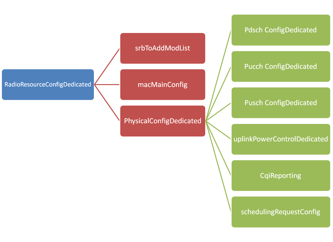
RRC Connection setup message include default configuration for SRB1 but can also include configuration information for PUSCH, PUCCH, PDSCH physical channels, CQI Reports, Sounding reference signal, antenna configuration and scheduling requests.
RRC Connection Setup message IEs layout


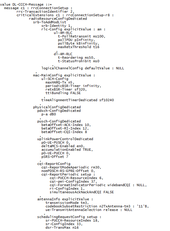
It is not possible in this blog to explain all the information carried by this message but an example message taken from test network is shown below 
RRC Connection Setup message 


RRC Connection Setup Complete

After receiving the RRC Connection setup message, UE complete the three way handshake procedure by sending 'RRC Connection setup complete' message and moves to RRC Connected mode. 

The message contains following information
  • selectedPLMN-Identity:  This is equal to 1 if UE selects the first PLMN from the plmn-identityList included in SIB1 or 2 if the second PLMN is selected in case UE belongs to more than one PLMN
  • dedicatedInfoNAS:  This IE is used to transfer UE specified NAS layer information between network and UE.


Example message is shown below

RRC Connection Setup complete message


For more LTE call flows, please check out this tool