5G NR Frequency Bands Table


Band Duplex Frequency Range (MHz) FR (Range) Notes
n1 FDD 1920 – 1980 / 2110 – 2170 FR1 PCS
n2 FDD 1850 – 1910 / 1930 – 1990 FR1 PCS 1900
n3 FDD 1710 – 1785 / 1805 – 1880 FR1 DCS 1800
n5 FDD 824 – 849 / 869 – 894 FR1 Cellular 850
n7 FDD 2500 – 2570 / 2620 – 2690 FR1 IMT-2000
n8 FDD 880 – 915 / 925 – 960 FR1 GSM 900
n12 FDD 699 – 716 / 729 – 746 FR1 Lower 700
n14 FDD 788 – 798 / 758 – 768 FR1 FirstNet (US)
n18 FDD 815 – 830 / 860 – 875 FR1 Japan
n20 FDD 832 – 862 / 791 – 821 FR1 EU Digital Dividend
n25 FDD 1850 – 1915 / 1930 – 1995 FR1 Extended PCS
n28 FDD 703 – 748 / 758 – 803 FR1 APT 700
n29 SDL 717 – 728 FR1 Supplemental DL
n30 FDD 2305 – 2315 / 2350 – 2360 FR1 WCS (US)
n34 TDD 2010 – 2025 FR1 China
n38 TDD 2570 – 2620 FR1 IMT-E
n39 TDD 1880 – 1920 FR1 China
n40 TDD 2300 – 2400 FR1 India, China
n41 TDD 2496 – 2690 FR1 Sprint US, China
n48 TDD 3550 – 3700 FR1 CBRS (US)
n50 FDD 1432 – 1517 / 1326 – 1400 FR1 Supplemental
n51 SDL 1427 – 1432 FR1
n53 TDD 2483.5 – 2495 FR1 US
n65 FDD 1920 – 2010 / 2110 – 2200 FR1 Extended IMT
n66 FDD 1710 – 1780 / 2110 – 2200 FR1 AWS
n70 FDD 1695 – 1710 / 1995 – 2020 FR1 AWS-4
n71 FDD 663 – 698 / 617 – 652 FR1 600 MHz (US)
n74 FDD 1427 – 1470 / 1475 – 1518 FR1
n75 SDL 1432 – 1517 FR1
n76 SDL 1427 – 1432 FR1
n77 TDD 3300 – 4200 FR1 C-Band (Global)
n78 TDD 3300 – 3800 FR1 Most common 5G
n79 TDD 4400 – 5000 FR1 China, Japan
n80 SDL 1710 – 1785 FR1
n81 SDL 880 – 915 FR1
n82 SDL 832 – 862 FR1
n83 SDL 703 – 748 FR1
n84 SDL 1920 – 1980 FR1
n86 SDL 1710 – 1780 FR1
n90 FDD 832 – 862 / 1427 – 1518 FR1 EU mix
n91 FDD 832 – 862 / 1427 – 1518 FR1
n92 SDL 1427 – 1518 FR1
n93 SDL 1427 – 1518 FR1
n94 SDL 1427 – 1518 FR1
n96 SDL 5925 – 6425 FR1 Wi-Fi 6E overlap
n257 TDD 26500 – 29500 FR2 mmWave
n258 TDD 24250 – 27500 FR2 mmWave
n259 TDD 39500 – 43500 FR2 mmWave
n260 TDD 37000 – 40000 FR2 mmWave
n261 TDD 27500 – 28350 FR2 US mmWave (Verizon)
n262 TDD 47200 – 48200 FR2 High mmWave
n263 TDD 28500 – 29500 FR2
n265 SDL 5925 – 7125 FR1 Wi-Fi 6E/7
n266 SDL 5925 – 7125 FR1 Wi-Fi 6E/7

Introduction to 6G

 Wireless technology has come a long way in recent years, and the latest generation, known as 6G, is set to take things to the next level. In this blog post, we'll provide an introduction to 6G wireless technology and give you a sense of what this exciting new development means for the future of wireless communications.


So, what exactly is 6G wireless technology? In short, it is the next generation of wireless technology that is expected to offer faster speeds, lower latency, and higher capacity than its predecessor, 5G. While 5G is still in the process of rolling out and being adopted by consumers and businesses around the world, researchers and industry experts are already looking ahead to the next generation of wireless technology.

One of the key benefits of 6G is that it is expected to offer significantly faster speeds than 5G. While 5G offers peak speeds of up to 10 Gbps, 6G is expected to offer speeds of up to 1 Tbps. This means that you'll be able to download and upload data much faster, with little to no lag.

In addition to faster speeds, 6G is also expected to offer lower latency, which refers to the time it takes for data to be transmitted from one device to another. This will be especially important for applications that require real-time communication, such as virtual reality and telemedicine.

Another key benefit of 6G is that it is expected to offer higher capacity, which means that it will be able to handle more devices and data traffic without experiencing congestion or interference. This will be particularly important as the number of connected devices continues to grow in the coming years.

While 6G is still in the early stages of development, it is clear that it has the potential to revolutionize the way we communicate and interact with each other. Whether you're a consumer, a business owner, or an industry professional, it's worth keeping an eye on this exciting new technology as it continues to evolve.

Dynamic Spectrum Sharing (DSS)

In the world of wireless communication, spectrum is a valuable resource. It is the range of frequencies that are used to transmit data over the airwaves, and the availability of spectrum determines the capacity and speed of a network. 

Traditionally, different types of communication have been allocated specific bands of spectrum. For example, cellular networks operate in the 700 MHz to 2700 MHz range, while Wi-Fi operates in the 2.4 GHz and 5 GHz bands. This approach has worked well for many years, but as the demand for data continues to grow, there is a need for more flexible and efficient use of spectrum. This is where Dynamic Spectrum Sharing (DSS) comes in. 

DSS is a technology that allows different types of communication to share the same band of spectrum. This brings a number of benefits to LTE networks, including: Increased capacity: By allowing different types of communication to share the same band of spectrum, DSS can increase the capacity of an LTE network. This is especially useful in areas where there is a high demand for data, such as city centers or busy airports. 

Improved coverage: DSS can also improve coverage in areas where there is a shortage of available spectrum. By sharing the spectrum with other types of communication, an LTE network can extend its reach and provide coverage to more people. More efficient use of spectrum: DSS allows for a more efficient use of spectrum, as it can be used by multiple types of communication rather than being dedicated to a single type. This can help to free up spectrum for other uses, such as 5G or Internet of Things (IoT) applications. 

DSS is an exciting technology that has the potential to bring greater flexibility and efficiency to LTE networks. As demand for data continues to grow, it will be an important tool in helping to meet the needs of users around the world.

PDCCH Blocking in LTE

In LTE, the Physical Downlink Control Channel (PDCCH) is used to carry control information for the downlink, such as scheduling assignments and hybrid automatic repeat request (HARQ) feedback. PDCCH blocking can occur when the network is overloaded and there are more scheduling assignments or control messages to be transmitted than there are available resources on the PDCCH. This can lead to delays in the transmission of control information, which can negatively impact the performance of the network. PDCCH blocking can also occur when there is interference on the channel or when there are problems with the channel quality.

UE Categories in LTE

 In LTE (Long-Term Evolution) networks, UE categories (or user equipment categories) are used to classify different types of mobile devices based on their capabilities and performance. UE categories till release 13 are shown in below Table 


Each UE category is defined by a set of capabilities and performance parameters, including the maximum data rates that the device is able to support, the type of modulation and coding schemes it is able to use, and the maximum transmits power it is able to use. These capabilities and performance parameters are specified in 3GPP (3rd Generation Partnership Project) standards.

The UE categories are used to determine the maximum data rates that a mobile device is able to achieve in an LTE network, as well as the type of modulation and coding schemes that it is able to use. Higher UE categories correspond to higher maximum data rates and more advanced modulation and coding schemes, while lower UE categories correspond to lower maximum data rates and less advanced modulation and coding schemes.


Nokia 5G

Unlike 2G, 3G and 4G, it is unlikely that 5G will be a single new Radio Access Technology (RAT) nor will it replace macro cells. It will be a combination of existing RATs in both licensed and unlicensed bands, plus one or more novel RATs optimized for specific deployments, scenarios and use cases. Check more details in below 5G white paper by Nokia

http://www.5gamericas.org/files/3614/3898/6583/Nokia_White_Paper_-_Looking_ahead_to_5G.pdf

PDCCH Order in LTE

PDCCH Order is a procedure to bring back uplink out-of-sync UE (user equipment) back to in-sync state incase there is downlink data available for it. This can happen in situation when the time alignment Timer  gets expired because there is no uplink and dowlink data transmission for some time and also when there is no Time alignment command recieved from eNB. Time Alignment timer basically controls how long the UE  is considered uplink time aligned.

For viewers to better understand PDCCH Order, here is an example :


    1. Lets assume we have a UE that is in RRC connected state
    2. There is uplink / downlink user data being transmitted for some time (like facebook activity etc)
    3. There is no more data to be transmitted. Time Alignment timer will start (expiry setting = 10 seconds). But remember the RRC Inactivity Timer will also start since there is no data activity but lets assume that our Inactivity Timer doesnt expire and we remain in RRC connected state for whole duration
    4. Time Alignment timer expires and UE is considered uplink out-of-sync now. At this point UE releases all PUCCH (scheduling resources, CQI configuration) and SRS resources. UE also flushes its HARQ buffers
    5. UE is still in RRC Connected state but it has no PUCCH/SRS resources as they were released previously. Now there is DL data in eNB buffer for UE (Like facebook notification or something) but first UE has to be brought back to in-sync state and also it needs to reconfigured again with PUCCH/SRS resources
    6. eNB sends PDCCH order to UE using DCI 1A format. This is basically signal to UE to perform the contention less RACH with preamble index already included in DCI 1A 
    7. UE sends MSG1 using RACH preamble acquired from PDCCH order (To read more about RACH procedure in LTE, click here)
    8. eNB sends RACH response with new time advance value so that UE can be uplink in-sync
    9. UE is in sync again ! 
    10. Next eNB sends RrcConnectionReconfiguration message which carries PUCCH/SRS as they were released when the time alignment timer was expired at step 4
    11. UE confirms reception of RrcConnectionReconfiguration message and now can resume uplink/downlink transmission of data

    Why UE needs time alignment ? 
    Due to different signal transmission paths and movement, UE can lose time synchronization to eNB subframe. eNB measures the time alignment of UE by measuring the difference between arrival time of PUCCH, PUSCH, SRS  to its own uplink subframe

                      How to build your own LTE Quadcopter

                      Having a quadcopter being controlled through LTE network without any limit in its flying range ( with an exception of battery backup and LTE coverage limit of course ) had always been a very appealing and interesting notion. There are few solutions available which are costly, So I wanted to come up with a cheaper alternative

                      First, lets begin with the main parts that will be needed to build on your LTE controlled Quadcopter.
                      See the required parts below

                      - Raspberry Pi (Amazon Link)   price ~$40
                      - F450 Quadcopter Kit (Ebay Link)  price ~$80
                      - LTE Dongle (Amazon Link)  price ~$50
                      - Battery Pack (Lipo) (Ebay Link) price ~$18
                      - Lipo Charger (Ebay Link) price ~$25
                      - Flight Controller CC3D (Ebay Link) price ~$13
                      - PC Gaming Joystick (Amazon Link) price ~$29

                      Some Background

                      A Quadcopter consists of four arms with a motor and propeller on the end of each arm. Two propellers are turning clockwise and the other two are turning counter-clockwise. There is a flight controller which keeps it leveled and converts your input commands into motion which it needs to fly. There are many cheap flight controllers available in the market. The one I used is called Open Flight CC3D. It costs only $13. Some other popular alternatives are

                      - Hobbyking KK2.1.5 Flight controller
                      - APM2.6 Ardupilot Flight Controller
                      - Naze32

                      Main parts of Quadcopter consists of a frame, a receiver, a flight controller, electronic speed controls, motors, and propellers. See below  for complete picture

                      Quadcopter Operation


                      Quadcopter motion (Throttle, Yaw, Pitch, Roll) commands are sent via RC Transmitter to RC Receiver and are  converted to PWM signals which are then used by flight controller to control the speed of Motors via Electronic Speed Conrollers (ESC). Most modern transmitters use a 2.4 Ghz frequency. RC receivers come mostly with 6 channels receivers.  Channels are the amount of things you can control. For example a four channel transmitter means you can only control four motors/servos/accessories. Mostly RC transmitter has 6 channels. These channels are controlling the Throttle, Yaw, Pitch, Roll, Aux 1, and Aux 2 (Aux can be used for different feature on your Quadcopter)

                      The output of the receiver is in the form  PWM signals. PWM stands for Pulse Width Modulation. PWM is a technique used to transmit data in the form of a varying pulse width. In the case of R/C electronics this time is usually 1-2 milliseconds.  For example, full throttle on your transmitter will send a 2 ms pulse to flight controller while zero throttle means puls of width 2 ms. Same rule applies to other controls on your transmitter. PWM pulse frequency is 20ms. The image below represents a typical PWM frame

                      PWM Signal output from RC Receiver

                      Replacing UHF Radio Link with IP Communication 

                      Main objective here is to replace the UHF radio link (2.4 Ghz) with IP communication network. Instead of using RC Transmitter we will use a regular PC gaming joystick to send control commands to Quadcopter through IP network. The commands are received by LTE dongle connected to Raspberry pi computer which converts these commands to PWM signals. The PWM signals are then used by CC3D flight controller to control the motion of flight.  See the below figure for end to end communication path

                      LTE Quadcopter

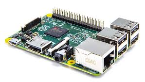
                      Note: If you are not familiar with raspberry pi, please visit https://www.raspberrypi.org/ to get some understanding .To put it short, It is is wonderful cheap little computer that can be used to make home media center, VPN, make robot and many more interesting projects. You can use almost any language on RPi though I always prefer to use Python as being very easy , high level and dynamic programming language

                      Raspberry Pi 2

                      Installing LTE modem on Raspberry Pi

                      I used Sakis3g script to install the drivers and application to configure the LTE modem. You can find more information at http://www.sakis3g.com/

                      How to communicate with LTE Dongle Private IP

                      One of the issue with LTE modem (dongle) is that it will be assigned private IP and will use Network Address Translation (NAT) to communicate to external world. NAT is the process where firewall assigns a public address to a network device inside private network. NAT save on the IP addresses as every network device (LTE dongle in our case) does not need a public address, and also it would hide these private devices from the outside world. For our quadcopter LTE dongle, it means that we wont be able to use the IP which is assigned to it in order to establish any IP communication to it. To overcome this problem we have to use our home Wifi router's port forwarding feature (application of NAT). Since our router's public IP is known to us ,therefore forwarding packet to our home PC coming from LTE quadcopter will not be an issue.

                      Let's assume that LTE dongle is assigned private IP 10.10.10.50 by the LTE network, Let's  also assume our home computer has private of 192.168.10.44 which was assigned by the Wifi router. Secondly our Wifi router has public IP of 173.75.180.60 which is known to us. We use TCP port 50050 for any communication from LTE quadcopter to Home PC. Now all we have to do is defining port forwarding table in our home wifi router. The basic rule that needs to be defined is to forward all incoming TCP packet with destination port of 50050 to our controller PC which has IP 192.168.10.44 and you are all set to have IP communication between Quadcopter and our home PC


                      Now here is how our end to end Communication will work

                      - Using Python's socket module function, Raspberry Pi (with LTE modem connected) will open a TCP connection to a port 50050 and IP 173.75.180.60.

                      - Python Socket Module on our home pc waits until a client connects to the port you specified

                      - Our home router forwards all incoming TCP packet with destination port of 50050 to our controller PC which has IP 192.168.10.44

                      - Once a socket is open, you can read from it like any IO object.

                      Below is the very basic python code that I used to do the communication between Raspberry Pi and home Computer as explained above. The code is just to give you a starting point while you can optimize the code below to have much better stabilized flight :)

                      Python Code on PC side


                      Python Code on Raspberry Pi side


                      Video Streaming from Quadcopter to Home Wifi Network 

                      Currently I am having trouble transmitting video from Quadcopter to Home Computer. I used  netcat utility to do the streaming but it makes  RPi reset every time. I believe I need to provide separate power bank. I will give update on it once successful, hopefully soon.


                      LTE Physical Uplink Control Channel (PUCCH)

                      Physical Uplink Control Channel (PUCCH) carries Uplink Control Information (UCI) which is basically bits and pieces of information that eNB requires from UE in order to understand what UE (user equipment) needs and carries other information like channel quality that UE is seeing in downlink,  etc

                      UCI is divided into three main sub branches i.e. Channel State Information (CSI), Scheduling Requests (SR) and HARQ ACK/NACK shown with some details as below


                      Note: 3GPP Release 8 and Release 9 UEs cannot transmit PUCCH and PUSCH on same TTI. If UE has to transmit UCI and data simultaneously within the same TTI, then PUSCH is used for UCI transmission but Release 10 allows simultaneous transmission of PUSCH and PUCCH

                      3GPP has defined different PUCCH formats to transfer different combinations of the information as can be seen in below table


                      A single PUCCH transmission always occupies 2 Resource Blocks
                      Frequency diversity of those two RBs is ensured by slot based PUCCH frequency hopping (See figure below) Each pair of RBs allocated to PUCCH can be used simultaneously by multiple UEs by
                      using different cyclic shifts and different orthogonal spreading codes


                      PUCCH Capacity Calculations

                      Remember every  RRC Connected UE needs to send CQI reports periodically!

                      Basic formula to calculate how many UEs (RRC Connected) are supported by eNB is

                      Number of UEs = Number Resource blocks used for CQI reporting x UEs Multiplexed per Resource Blocks x CQI reporting periodicity

                      The CQI reporting periodicity (in subframes) are determined based on the parameter
                      cqi-pmi-ConfigIndex given in Table 7.2.2-1A for FDD in 3GPP TS 36.213

                      Example
                      Lets assume we have reserved  5 resource blocks (eNB Parameter) for CQI reporting and 6 UEs can be multiplexed per resource blocks. Also lets assume that CQI periodicity is 40 ms then the total number of RRC Connected UEs that eNB can support is as below

                      Number of UEs= 5 * 6 * 40 = 1200


                      Note: This is not the only limitation for how many RRC Connected users eNB can support. The above capacity calculation is just to explain the requirement atleast from UE CSI reporting perspective


                      Connected Mode DRX


                      We know that 2G and 3G terminal uses discontinuous reception in idle mode. In LTE the tradition has continued and we have similar DRX in idle mode but in addition to that we also have DRX in RRC mode.  In LTE, when there is no data to receive or transmit in RRC connected mode, UE would switch off its transceiver for a very short interval. It will start similar "wake up and sleep " cycle. During the wake up period, it will keep monitoring PDCCH channel for UL or DL grants whereas the sleep periods will improve the battery savings

                      Without Connected Mode DRX 

                      The main goal of Connected mode DRX is to minimize battery consumption by discontinuous monitoring of PDCCH channel. Without DRX, UE has to monitor PDCCH channel every time. This results in high battery consumption as shown below


                      With Connected Mode DRX

                      With DRX enabled in connected mode, UE only monitors PDCCH channel when it is awake during the sleep/wakeup cycles as seen below. During the sleep time, UE doesn't monitor PDCCH channels which results in energy savings. All the DL grants are delayed to nearest wake up period


                      Important DRX Parameters/Timers 

                      Some of the important parameters used in configuring the DRX for UE are shown below. The parameters are transferred to UE through RRC reconfiguration message


                      Basic Scenario

                      To better understand these parameters, see the below picture which shows each parameter

                      1.  UE is in RRC Connected mode and is continuously monitoring PDCCH. At this point, there is DL Grant and downlink data. The DRX inactivity timer and the main RRC Inactivity timer are restarted
                      2. There is UL grant for UE. With DL Grant both DRX and RRC inactivity timers are restarted. 4 ms later UE sends data in uplink
                      3. The DRX Inactivity timer is expired since there were no further grants in uplink or downlink. Though UE was constantly monitoring PDCCH. UE now enters the short DRX cycle. The battery savings have just started
                      4.  The DRX short cycle timer got expired therefore UE will end up its short DRX cycle and enter the long DRX cycle
                      5. The main RRC inactivity timer got expired since there was no activity in uplink or downlink for the duration for RRC Inactivity timer. The UE will go to RRC IDLE state. In idle state UE will use paging DRX cycle


                      HARQ Retransmissions Scenario

                      In the above basic scenario it may seem complicated to include HARQ retransmission's scenarios, so here is another example below
                      1.  UE is in RRC Connected mode and is continuously monitoring PDCCH channel. At this point, there is DL Grant and downlink data. The DRX and RRC inactivity timer is restarted ( RRC Inactivity not shown here)
                      2. There is UL grant for UE. With DL Grant both DRX and RRC inactivity timers are restarted 4ms later UE sends data in uplink. And after additional 4ms later ACK is sent by eNB
                      3. There is DL grant for UE with DL data. For some reason UE is not able to decode the data. 4ms later UE will send NACK towards eNB. Harq RTT timer is started which has fixed duration of 8ms. Now UE is expecting retransmission in downlink
                      4. HARQ RTT got expired which will trigger the DRX retransmission timer as the retransmission is expected
                      5. There is DL grant with retransmission data. This time UE is able to decode it. 4ms later UE sends ACK in uplink. Note DL grant for retransmission data does not restart DRX inactivity timer
                      6. DRX retransmission timer expires and UE enters the short DRX cycle


                      Key points:
                      •  DRX cycles are synchronized at UE and eNB side i.e. eNB knows when UE is in DRX sleep or awake period so that it can schedule UE accordingly
                      • When UE is in DRX sleep state, it cannot read PDCCH channel therefore, the downlink grants must be delayed to nearest wake cycle as eNB is already aware of this UE DRX cycle. The introduces delay in dowlink transmission
                      • Uplink transmission is not affected as UE can send SR in uplink whenever it wants i.e. UE is in DRX sleep period and it has uplink data so it will just wake up and send SR to receive UL grants from eNB. 
                      • Other than the timers/parameters mentioned above, eNB MAC can also control UE DRX by transmitting MAC CE DRX commands


                      LTE in Unlicensed Spectrum (LTE-U)

                      LTE in Unlicensed spectrum (LTE-U) is one of the hot topics in 2015 telecom industry. LTE-U extends the benefits of LTE and LTE Advanced to unlicensed spectrum, enabling mobile operators to offload data traffic onto unlicensed frequencies more efficiently.

                      LTE-U also poses major challenges to WiFi as both will operate in an unlicensed and un-controlled spectrum. However, various techniques have been developed to share the unlicensed spectrum fairly between LTE and WiFi technologies. Please check below white paper from Nokia for more details on LTE-U

                      RSRP, RSSI and RSRQ

                      In LTE network, UEs need to measure signal strength of its own and neighbor cells constantly, during idle, connected mode or handovers in order to keep the signal quality constant. UE measures RSRP and RSRQ in LTE

                      Reference Symbol Received Power (RSRP):

                      • RSRP is the linear average of the downlink reference signals across the channel bandwidth 
                      • RSRP provides information about signal strength and  gives no indication of signal quality 
                      • RSRP measurements are used in handover, cell selection and cell re-selections 
                      • The reporting range of RSRP is defined from -140 dBm to -44 dBm with 1 dB resolution as shown in table below
                      RSRP measurement report mapping (3GPP Reference: TS 36.133)

                      Received Signal Strength Indicator (RSSI):

                      • RSSI represents the total received wide-band power by UE
                      • RSSI is measured only in symbols containing Reference signals 
                      • RSSI includes power from serving cell as well as co-channel interference and noise
                      • RSSI helps in determining interference and noise information 
                      • RSSI is never reported by UE

                      Reference Signal Received Quality (RSRQ):

                      • RSRQ indicates quality of received reference signal. RSRQ measurement and calculation is based on RSRP and RSSI since RSRP determines signal quality and RSSI determines co-channel interference and noise. RSRQ formula is shown below (N represents number of resource blocks)
                      • The reporting range of RSRQ is defined from -19.5 dB to -3 with 0.5 dB resolution
                      RSRQ measurement report mapping (3GPP Reference: TS 36.133)

                      Example

                      Lets try to calculate RSRP, RSSI and RSRQ for one very simple case of one resource block with 12 sub carriers and 0.5 ms in time domain. For sake of simplicity, lets assume the power of reference symbols  (shown by red square) and power of other symbols carrying other data channels (shown by blue square) is same i.e. 0.021 watt


                      Since RSRP is linear average of downlink reference signal for given channel bandwidth therefore
                      RSRP = 10*log (0.021*1000) = 13.2 dBm

                      While RSSI is total received wide-band power. Therefore we have to add power of all 12 carriers in the given resource block
                      RSSI = 10*log(0.021*1000)+10*log(12) = 24 dBm

                      RSRQ is now simple ratio of RSRP to RSSI with N=1
                      RSRQ = 10*log(0.021/(12*0.021)) = -10.79 dB


                      Why do we use dBm as a unit of Power

                      We use decibels-milliwatts to measures power levels in telecommunication and other fields instead of Watt. The reason to use logarithmic scale is that it helps in reducing massive values to smaller number

                      Example : 0.00000000000080 watt which apparently looks very small value but
                      can still be received by antenna. The logarithmic value is just -91 dbm by using below formula
                      P (dBm) = 10 x Log (1000*P)

                      dBm vs dB

                      dB is ratio between two power values while dBm is used to express an absolute value of power. So when we mention RSRP and RSSI we shall always use dBm since we are talking about absolute power values but we need to use dB with RSRQ since it is the ratio of RSRP to RSSI

                      Overview of LTE 3GPP releases


                      Release 8 - LTE Introduced  

                      Release frozen in Dec 2008 

                      It was 3GPP release 8 when LTE was introduced for the very first time.  All the releases following only enhanced the technology.

                      Based on release 8 standardization, following were the main achievements
                      • High peak data rates : Up to 300 Mbps in downlink and 75 Mbps in uplink when using 4x4 MIMO and 20 MHz bandwidth
                      • High spectral efficiency 
                      • Flexible bandwidths: 1.4 MHz, 3 MHz, 5 MHz, 10 MHz, 15 MHz and 20 MHz
                      • Short round trip time: 5 ms latency for IP packets in ideal radio conditions
                      • Simplified Architecture
                      • OFDMA in downlink and SC-FDMA in uplink
                      • All IP network 
                      • MIMO multiple antenna scheme
                      • Operation in paired (FDD) and unpaired spectrum (TDD)


                      Release 9 - Enhancement to LTE

                      Release frozen in Dec 2009

                      The initial enhancements were included to LTE in release 9. These were in fact the improvements which were left behind from release 8 or perhaps provided some minor improvements. These improvements are listed below with brief description

                      PWS (Public Warning System): Public should always receive timely and accurate alerts related to natural disasters or other critical situations. Commercial Mobile Alert System (CMAS) was introduced in release 9 in addition to ETWS introduced in release 8

                      Femto Cell: Femto cell is basically a small cell used in offices or homes and connected to providers’ networks through landline broadband connection. 3G Femto cells are deployed around world and in order for LTE users to take advantage of femto cell, new requirements were added to release 9

                      MIMO Beam forming:
                       Beamforming is used to increase cell edge throughput by directing beam towards specific UE by position estimation at eNB. In release 8, LTE supported single layer beam forming based on user-specific Reference Symbols. In release 9, single layer beam forming has been extended to multilayer beam forming

                      Self Organizing Networks (SON): SON means self installation, optimization and healing of networks in order to reduce manual work and cost associated with technical support. The idea of SON was introduced in release 8 though the focus was more towards eNBs self configuration where as in release 9, requirements for self optimization were also added

                      eMBMS: With  Multimedia broadcast Multicast Services (MBMS), operators have capability to broadcast services over LTE network. The idea is not novel to the LTE and  has been used in legacy networks as well but for LTE, the MBMS channel has evolved from data rate and capacity perspective. The MBMS was already defined at physical layer in release8 but with release 9, higher layer and network layer aspects were completed

                      LTE Positioning: Three position methods are specified in LTE release 9 i.e. Assisted GPS (A-GPS), Observed Time difference of arrival (OTDOA) and Enhanced Cell ID (E-CID). The goal is to improve the accuracy of user locations in case of emergency scenarios where the user itself is unable to disclose his whereabouts


                      Release 10 - LTE  Advanced

                      Release Frozen in March 2011

                      THE LTE-Advanced specifications in release 10 includes significant features and improvements to fulfil ITU IMT-Advanced requirements which sets higher speeds than what UE can achieve from 3GPP release 8 specifications. Some key requirements laid down by IMT-Advanced are as below

                      - 1 Gbps DL / 500 Mbps UL throughput
                      - High spectral efficiency
                      - Worldwide roaming

                      Following are some significant improvements in release 10

                      Enhanced Uplink multiple access: Release 10 introduces clustered SC-FDMA in uplink. Release 8 SC-FDMA only allowed carriers along contiguous block of spectrum but LTE-Advanced in release 10 allows frequency-selective scheduling in uplink

                      MIMO enhancements: LTE-Advanced allows upto 8x8 MIMO in downlink and on the UE side it allows 4X4 in uplink direction

                      Relay Nodes: In order to decrease coverage loop holes, Relay nodes are one of the features proposed in release 10. The relay nodes or low power enbs extending the coverage of main eNB in low coverage environment. The relay nodes are connected to Donor eNB (DeNB) through Un interface. 

                      enhanced inter-cell interference coordination (eICIC): 
                      eICIC introduced in 3GPP release 10 to deal with interference issues in Heterogeneous Networks (HetNet). eICIC mitigates interference on traffic and control channels. eICIC uses power, frequency and also time domain to mitigate intra-frequency interference in heterogeneous networks

                      Carrier Aggregation (CA): CA introduced in release 10 is a cost effective way for operators to utilize their fragmented spectrum spread across different or same bands in order to improve end user throughput as required by IMT-Advanced. User throughput is increased by sending data simultaneously over two or more carriers. LTE-Advanced supports bandwidths up to 100 MHz formed by combining up to five 20MHz component carriers. Contiguous and non-contiguous carriers may be aggregated

                      Support for Heterogeneous Networks: The combination of large macro cells with small cells results in heterogeneous networks. Release 10 intended to layout the detail specification for heterogeneous networks

                      SON Improvements: Release 10 provides enhancements to SON features introduced in release 10 which also considers self healing procedures


                      Release 11 - Enhancement to LTE Advanced

                      Release Frozen in september 2012

                      Release 11 includes enhancements to LTE Advanced features standardized in release 10. Some of the important enhancements are listed below 

                      Carrier Aggregation enhancements: Following are the major enhancements to carrier aggregation in release 11
                      - Multiple timing advances (TAs) for uplink carrier aggregation
                      - Non contiguous intra band carrier aggregation
                      - physical layer changes for carrier aggregation support in TDD LTE

                      Coordinated multipoint transmission and reception (CoMP): With CoMP the transmitter can share data load even if they are not collocated. Though they are connected by high speed fiber link

                      ePDCCH: New enhanced PDCCH introduced in 3GPP release 11 to increase control channel capacity. ePDCCH uses PDSCH resources for transmitting control information unlike release 8 PDCCH which can only use control region of subframes

                      Network based Positioning: In release 11, support for uplink positioning is added by utilizing Sounding reference signals for time difference measurements taken by many eNBs. 

                      Minimization of drive test (MDT): Drive tests are always expensive. To decrease dependency on drive tests, new solutions introduced which are independent of SON though much related. MDT basically relies on information provided by UE

                      Ran overload control for Machine type communication: For machine type devices new mechanism has been specified in release 11 where network in case of mass communication from devices can bar some devices to send connection request to network

                      In Device Co Existence: Now a days, all mobile devices would usually carry multi radio transceivers like for LTE, 3G, Bluetooth, WLAN etc. Now this co existence results in interference. To mitigate this interference, release 11 has specified solutions as mentioned below
                      - DRX based time domain solutions
                      - Frequency domain solutions
                      - UE autonomous denials 

                      Smartphone Battery saving technique: Many applications on smartphones generate background traffic which consumes battery power. Release 11 specifies a method where UE can inform network whether it needs to be operated in battery saving mode or normal mode and based on UE request network can modify DRX parameters


                      Release 12 - Further enhancement to LTE Advanced

                      Release Frozen in June 2014

                      Small cells enhancements: Small cells were supported since beginning with features like ICIC and eICIC in release 10. Release 12 introduces optimization and enhancements for small cells including deployments in dense areas. Dual connectivity i.e. inter-site carrier aggregation between macro and small cells is also a focus area

                      Carrier aggregation enhancements: Release 12 now allows carrier aggregation between co-located TDD and FDD carriers. In addition to carrier aggregation between TDD and FDD, there is also now three carrier aggregations possible for total of 60 Mhz spectrum aggregated

                      Machine Type communication (MTC): Huge growth is expected in machine type communication in coming years which can result in tremendous network signaling, capacity issues. To cope with this, new UE category is defined for optimized MTC operations

                      Wifi integration with LTE: With integration between LTE and Wifi, operators will have more control on managing WiFi sessions. In release 12, the intent is to specify mechanism for steering traffic and network selection between LTE and WiFI 

                      LTE in unlicensed spectrum: An LTE operation in unlicensed spectrum is one of the study items in release 12. Operations in Bandwidth rich unlicensed spectrum brings many benefits to operators like increase in network capacity, load and performance


                      Release 13 - Meeting the growing throughput demand

                      Ongoing - Release expected to be frozen in  Dec 2015

                      Carrier Aggregation enhancements: The goal in release 13 is to support carrier aggregation of upto 32 CC (component carriers) where as in release 10, the carrier aggregation was introduced with support of only upto 5 CC.

                      enhancements for Machine-Type communication (MTC): Continuing from release 12, there are further enhancements in MTC, a new low complexity UE category is being defined to provide support for reduced bandwidth, power and support long battery life. 

                      LTE in unlicensed spectrum enhancements: The focus in release 13 is the aggregation of primary cell from licensed spectrum with secondary cell from unlicensed spectrum to meet the growing traffic demand

                      Indoor Positioning: In release 13 there is work going on improving existing methods of indoor positioning and also exploring new positioning methods to improve indoor accuracy

                      Enhanced multi-user transmission techniques: Release 13 also covers potential enhancements for downink multiuser transmission using superposition coding

                      MIMO enhancements: Upto 8 antenna MIMO systems are currently supported, the new study in this release will look into high-order MIMO systems with up to 64 antenna ports