RRC Connection Establishment in LTE


Background

The first thing UE does after switching on is to synchronize to each frequency and check whether this frequency is from the right operator to which it wants to connect to. UE does this by going through very initial synchronisation process. Once synchronized, UE reads the master information block and System information blocks to check if this is the right PLMN. Lets assume it finds that PLMN value to be correct and so UE will proceed with reading System information block 1 and System information block 2. The next step is known as Random Access Procedure in which the network for the first time knows that some UE is trying to get access and the network provides temporary resources to the UE for initial communication.


Once the Random Access procedure is successfully completed, next is RRC connection establishment procedure which configures SRB1 for UE and let UE inform the network what exactly it wants i.e. Attach, Service Request, Tracking area update etc. RRC connection establishment is 3 way handshake procedure comprising of following messages.

- RRC Connection Request
- RRC Connection Setup
- RRC Connection Setup complete


RRC Connection Request (RACH Msg3)

 Actually the RACH Msg3 is the first message of RRC connection establishment procedure. Once the UE has obtained temporary resources via MSG2 in RACH process , its now ready to send 'RRC connection request' message using UL-SCH to eNodeB. UE is identified by temporary C-RNTI assigned in RACH Msg2
  • The message contains following information
    • UE identity (TMSI or Random Value )
      • TMSI is used if UE has previously connected to the same network. With TMSI value, UE is identified in the core network 
      • Random value is used if UE is connecting for the very first time to network. Why we need random value or TMSI? Because there is a possibility that Temp-CRNTI has been assigned to more than one UEs in previous step, due to multiple requests coming at same time (Collision scenario explained later)
    • Connection establishment cause: This shows the reason why UE needs to connect to network
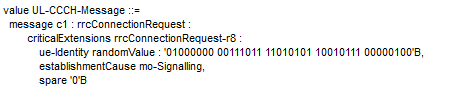

RRC Connection Request message


RRC Connection Setup 

The RRC connection setup message contain configuration details for SRB1 so that later messages can  be transferred via SRB1. Remember the SRB2 is always configured after the security activation.

RRC Connection setup message include default configuration for SRB1 but can also include configuration information for PUSCH, PUCCH, PDSCH physical channels, CQI Reports, Sounding reference signal, antenna configuration and scheduling requests.
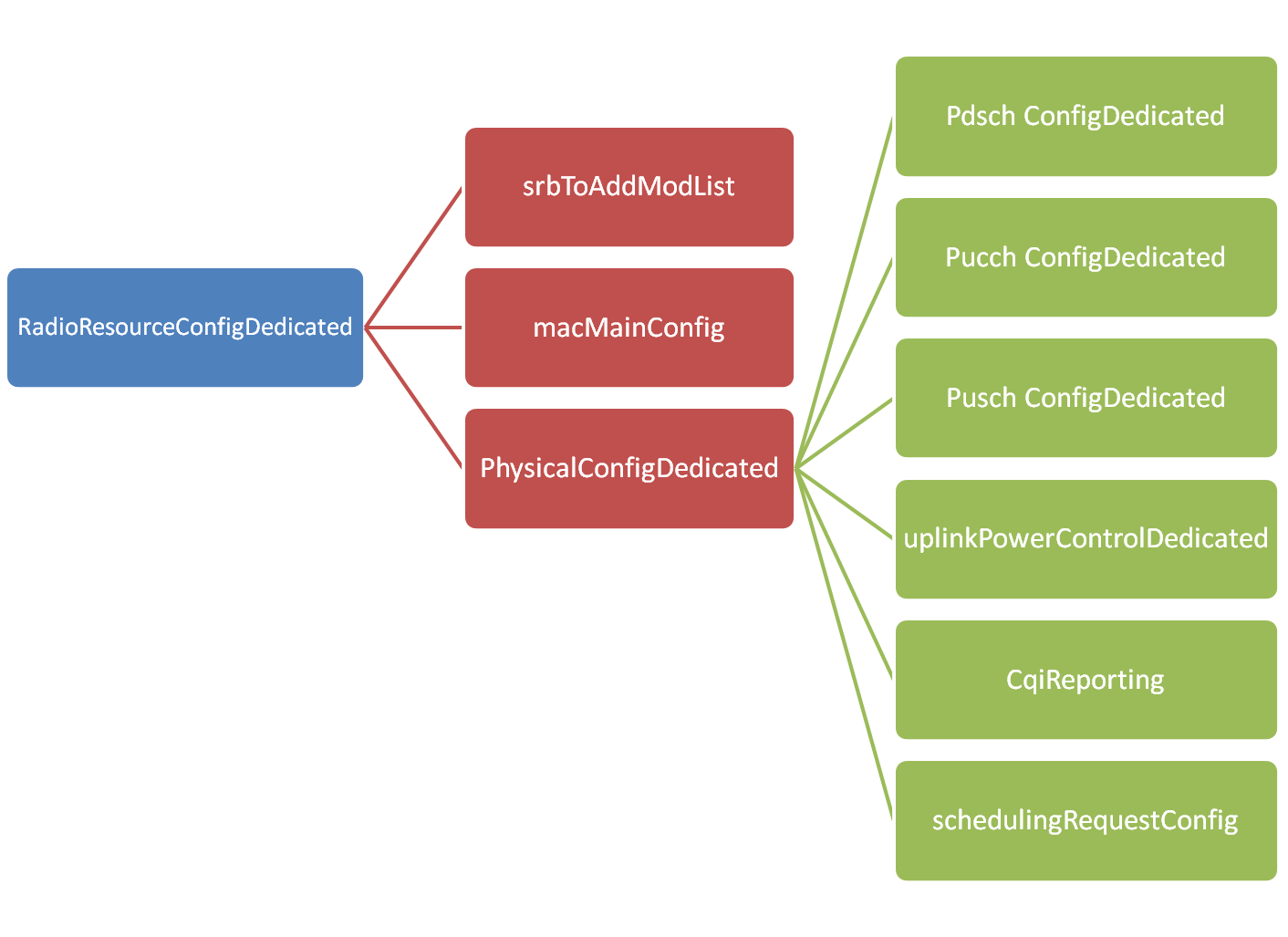
RRC Connection Setup message IEs layout


It is not possible in this blog to explain all the information carried by this message but an example message taken from test network is shown below 
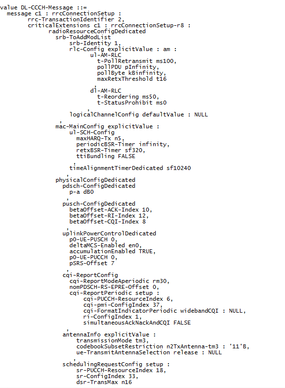
RRC Connection Setup message 


RRC Connection Setup Complete

After receiving the RRC Connection setup message, UE complete the three way handshake procedure by sending 'RRC Connection setup complete' message and moves to RRC Connected mode. 

The message contains following information
  • selectedPLMN-Identity:  This is equal to 1 if UE selects the first PLMN from the plmn-identityList included in SIB1 or 2 if the second PLMN is selected in case UE belongs to more than one PLMN
  • dedicatedInfoNAS:  This IE is used to transfer UE specified NAS layer information between network and UE.


Example message is shown below
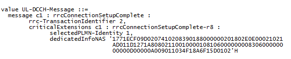
RRC Connection Setup complete message


For more LTE call flows, please check out this tool

Basics of scheduling in LTE

Scheduling is the process through which eNB decides which UEs should be given resources to send or receive data . In LTE, scheduling is done per subframe level (i.e. each 1 ms TTI)

Before getting into basics of scheduling, it is important to understand following key terms:

CQI:

CQI (Channel quality indicator) is a four digit value sent to eNB by UE as a feedback for downlink channel.CQI informs eNB about the channel quality in downlink. This helps eNB to allocate proper MCS (Modulation and coding scheme) and RB (Resource block) for UE

BSR:

BSR (Buffer Status Report) is a UE way of informing network that it has certain data in its buffer and it requires grants to send this data

QoS:

QoS (Quality of Service) defines how a particular user data should be treated in the network. QoS is implemented between UE and PDN Gateway and is applied to a set of bearers.  e.g. VoIP packets are prioritized by network compared to web browser traffic.


Now let's see how the scheduling works
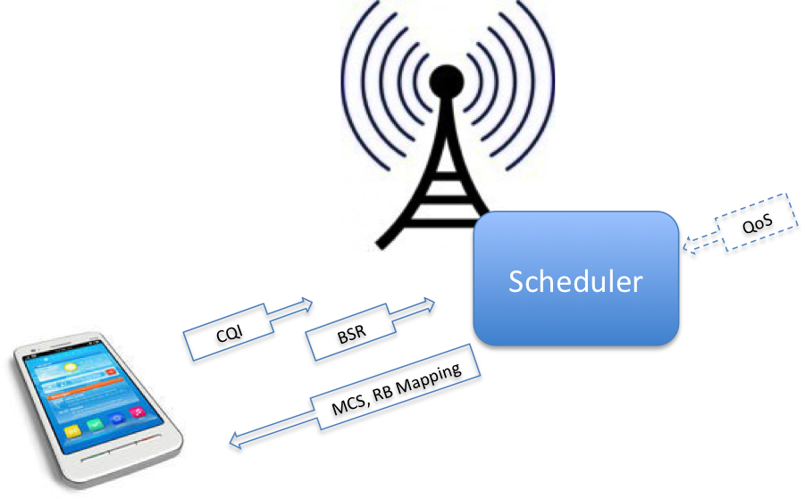
  • UE computes the CQI value from downlink channel and sends it to the eNB
  • UE sends BSR reports to eNodeB
  • Based on BSR, CQI and UE QoS, eNodeB computes MCS value and PRB mapping information and send it to the UE in downlink

Factors that affects scheduling: 

  • Traffic Volume: Schedules those UEs with bearers waiting data in buffer
  • QoS Requirement: Schedules and allocates resources to UE to meet its QoS requirement
  • Radio Conditions: Schedules resources for UE that best suits its radio environment


Physical Control Format Indicator Channel (PCFICH)

Introduction

'Channels' are used to differentiate different kinds of traffic on radio path. For example, data channels carry users traffic (Youtube, Skype data etc) and control channels carry signaling traffic to manage radio resources, setting up connection etc

The Physical Control Format Indicator Channel (PCFICH) is one of the control channels that works at physical layer. It is used to dynamically indicate the number of symbols to be used for PDCCH.

Why do we need PCFICH ? 

With the help of PCFICH channel, following scenarios are possible:

- Use less symbols for PDCCH if there are a few users with high data rates. Thus leaving more resource elements to be used for user plane data (PDSCH)

- Use more symbols for PDCCH if there are many users with lower data rates e.g VoIP calls in the cell, thus allowing more users capacity.

Signalled value

PCFICH signalled value depends on channel bandwidth. For channel bandwidth of 3MHz up to 20 Mhz it can carry value of 1, 2 or 3. But for 1.4 Mhz channel bandwidth it can carry value of 2, 3 or 4. Because in case of 1.4 Mhz bandwidth, there are few subcarriers in frequency domain.Therefore, more space is required in time domain to carry PDCCH symbols

Location of PCFICH symbols on Resource Grid

PCFICH occupies 16 resource elements in frequency domain.  These resource elements are divided into groups of four quadruplets distributed within first OFDMA symbol of each 1 ms subframe. The exact position of PCFICH can be measured from Cell ID and bandwidth using formula given in 3GPP spec 36.211 as below

Where
NRBSC = Number of frequency carriers per Resource block
NDLRB = Number of resource blocks per bandwidth
NcellID  = Physical Cell id

It may look complicated but lets try to understand it with simple example

Lets suppose
Physical Cell id = 20
Bandwidth = 10Mhz  (NDLRB = 50)

Then according to 3GPP Formula

k_Bar = (12/2).(20 mod 2*50) = 6*20 = 120

Then the four PCFICH mapping values are below 

120
120 + (50/2)*(12/2) = 270
120 + 2*(50/2)*(12/2)  = 420
120 + 3*(50/2)*(12/2) = 570

Visit LTE Resource Grid generator to validate above mapping values (Enter Cell id = 20 and Bandwidth = 10Mhz)
http://paul.wad.homepage.dk/LTE/lte_resource_grid.html 

Random Access Procedure in LTE

Background

When you switch on smartphone for the very first time, it will start searching for the network. There is a possibility that there are many networks or to put in other words , there are many frequencies from different operators available in the air to which UE (user equipment) can connect. Therefore, UE  needs to synchronize to each frequency and check whether this is frequency from the right operator to which it wants to connect to. UE does this by going through very initial synchronisation process. Once synchronized UE reads the master information block and System information blocks to check whether this is the right PLMN. Lets assume that it finds that PLMN value to be correct and so UE will proceed with reading System information block 1 and System information block 2. The next step is known as Random Access Procedure in which the network for the first time knows that some UE is trying to get access.

At this stage, UE does not have any resource or channel available to inform network about its desire to connect to it so it will send its request over the shared medium. Now there are two possibilities at this stage, either there are many other UEs in the same area (same cell) sending same request in which there is also a possibility of collision among the requests coming from various other UEs. Such random access procedure is called contention based Random access procedure. In second scenario, network can inform UE to use some unique identity to prevent its request from colliding with requests coming from other UEs. The second scenario is called contention free or non contention based random access procedure.

RACH preambles

The concept of RACH preamble though a little confusing is important in understanding the random access procedure.

When UE sends the very first message of random access procedure to some network, it basically sends specific pattern or signature which is called RACH preambles. The preamble value differentiate requests coming from different UEs. But if two UEs uses same RACH preambles at same time then there can be collision. There are totally 64 such patterns or signature available to the UE for the very first message of random access procedure and UE will decide any one of them randomly for contention-based random access procedure but for non-contention based procedure, actually network will inform UE about which one to use

In case, when UE goes from idle state to RRC connected state, there is no way for network to inform UE about which preamble out of 64 values should be used. Therefor UE has no choice but to use one of the preambles randomly which also result in possibility of collision if the same preamble is being used by another UE, provided the requests comes at same time (same frame)

In another scenario  if UE has to take handover to another eNB, in this case actually the UE can be informed about which preamble it can use, since UE is already in connected state

Steps of Random access procedure

Random access procedure consist of four steps explained below (Only contention based procedure is shown below)


Step 1: Msg1

  • UE selects one of the 64 available RACH preambles
  • Now UE also needs to give its own identity to the network so that network can address it in next step. The identity which UE will use is called RA-RNTI (Random access radio network temporary identity). Basically its not some value sent by UE but interestingly RA RNTI is determined from the time slot number in which the preamble is sent
  • If UE does not receive any response from the network, it increases its power in fixed step and sends RACH preamble again

Step 2: Msg2

  • eNodeB sends "Random Access Response" to UE on DL-SCH (Downlink shared channel) addressed to RA-RNTI calculated from the timeslot in which preamable was sent, as explained in step 1 (about RA-RNTI calculation)
  • The message carries following information 
    • Temporary C-RNTI: Now eNB gives another identity to UE which is called temporary C-RNTI (cell radio network temporary identity) for further communication
    • Timing Advance Value: eNodeB also informs UE to change its timing so it can compensate for the round trip delay caused by UE distance from the eNodeB
    • Uplink Grant Resource: Network (eNodeB) will assign initial resource to UE so that it can use UL-SCH (Uplink shared channel)

Step 3: Msg3 

  • Using UL-SCH, UE sends "RRC connection request message" to eNodeB
  • UE is identified by temporary C-RNTI (assigned in the previous step by eNodeB)
  • The message contains following
    • UE identity (TMSI or Random Value )
      • TMSI is used if UE has previously connected to the same network. With TMSI value, UE is identified in the core network 
      • Random value is used if UE is connecting for the very first time to network. Why we need random value or TMSI? Because there is possibility that Temp-CRNTI has been assigned to more than one UEs in previous step, due to multiple requests coming at same time (Collision scenario explained later)
    • Connection establishment cause: The shows the reason why UE needs to connect to network

Step 4: Msg4

  • eNodeB responds with contention resolution message to UE whose message was successfully received in step 3. This message is address towards TMSI value or Random number (from previous steps) but contains the new C RNTI which will be used for the further communication

Collision Scenario

The above example didn't consider any collision. Collision can occur because of following example scenario
  • Lets assume two UEs send same RACH preamble at same time in step 1
  • Same Temp C-RNTI and up-link grant will be received by two UEs in step 2
  • In step 3 eNodeB may be able to receive Msg3 from only one UE or none of them due to interference. 
  • In step 4 the UE which does not receive Msg4 from eNodeB will back-off after expiration of RACH specific timers. Possibility is also that none of them receive Msg4 
  • UE which receive msg4 will move to next step and decode RRC connection setup message


For more LTE call flows, please check out this tool

GPRS Tunneling Protocol (GTP) in LTE

Introduction

GPRS Tunneling protocol is an important IP/UDP based protocol used in GSM, UMTS and LTE core networks. It is used to encapsulate user data when passing through core network and also carries bearer specific signalling traffic between various core network entities. This protocol has several advantages which will be discussed later.


GPRS Tunneling Protocol Types


Why is GTP used in LTE?

  • It provides mobility. When UE is mobile, the IP address remains same and packets are still forwarded since tunneling is provided between PGW and eNB via SGW 
  • Multiple tunnels (bearers) can be used by same UE to obtain different network QoS
  • Main IP remains hidden so it provides security as well
  • Creation, deletion and modification of tunnels in case of GTP-C

GTP Interfaces in LTE

In LTE, version 2 is used for GTP-C and version 1 is used for GTP-U
In simple LTE network implementation, GTP-v2 is used on S5 and S11 interfaces and GTPv1 is used on S1-U, S5, X2-U interfaces (as shown below). In inter-RAT and inter PLMN connectivity, S3, S4, S8, S10, S12 and S16 interfaces also utilize GTP protocols

How GTP-U Works ?

GTP-U encapsulation of UE user plane traffic can be easily understood by taking any simple example. Lets see what happens when IP packet generated by UE reaches to eNodeB and is then forwarded to SGW.

Consider any application on UE creates an IP/TCP packet. This packet consist of actual data by application, TCP or UDP header and then IP field information which has source address of UE and destination address of application server (e.g. Facebook)

When the eNodeB receives this packet over air interface, it will put the IP packet inside GTP header which has information related to tunnel IDs. Then further, it is encapsulated inside UDP and IP header and forwarded as ethernet frame towards SGW. Here the IP header contains eNodeB IP as a source address and SGW IP as a destination address

GTP-C signalling messages

As GTP-Cv2 in LTE is used for tunnel management, some of the signalling messages are listed below which use GTP-Cv2 protocol 


Please check Table 6.1-1(3GPP TS 29.274) for more detailed list of GTP-C based messages.