How to build your own LTE Quadcopter

Having a quadcopter being controlled through LTE network without any limit in its flying range ( with an exception of battery backup and LTE coverage limit of course ) had always been a very appealing and interesting notion. There are few solutions available which are costly, So I wanted to come up with a cheaper alternative

First, lets begin with the main parts that will be needed to build on your LTE controlled Quadcopter.
See the required parts below

- Raspberry Pi (Amazon Link)   price ~$40
- F450 Quadcopter Kit (Ebay Link)  price ~$80
- LTE Dongle (Amazon Link)  price ~$50
- Battery Pack (Lipo) (Ebay Link) price ~$18
- Lipo Charger (Ebay Link) price ~$25
- Flight Controller CC3D (Ebay Link) price ~$13
- PC Gaming Joystick (Amazon Link) price ~$29

Some Background

A Quadcopter consists of four arms with a motor and propeller on the end of each arm. Two propellers are turning clockwise and the other two are turning counter-clockwise. There is a flight controller which keeps it leveled and converts your input commands into motion which it needs to fly. There are many cheap flight controllers available in the market. The one I used is called Open Flight CC3D. It costs only $13. Some other popular alternatives are

- Hobbyking KK2.1.5 Flight controller
- APM2.6 Ardupilot Flight Controller
- Naze32

Main parts of Quadcopter consists of a frame, a receiver, a flight controller, electronic speed controls, motors, and propellers. See below  for complete picture

Quadcopter Operation


Quadcopter motion (Throttle, Yaw, Pitch, Roll) commands are sent via RC Transmitter to RC Receiver and are  converted to PWM signals which are then used by flight controller to control the speed of Motors via Electronic Speed Conrollers (ESC). Most modern transmitters use a 2.4 Ghz frequency. RC receivers come mostly with 6 channels receivers.  Channels are the amount of things you can control. For example a four channel transmitter means you can only control four motors/servos/accessories. Mostly RC transmitter has 6 channels. These channels are controlling the Throttle, Yaw, Pitch, Roll, Aux 1, and Aux 2 (Aux can be used for different feature on your Quadcopter)

The output of the receiver is in the form  PWM signals. PWM stands for Pulse Width Modulation. PWM is a technique used to transmit data in the form of a varying pulse width. In the case of R/C electronics this time is usually 1-2 milliseconds.  For example, full throttle on your transmitter will send a 2 ms pulse to flight controller while zero throttle means puls of width 2 ms. Same rule applies to other controls on your transmitter. PWM pulse frequency is 20ms. The image below represents a typical PWM frame

PWM Signal output from RC Receiver

Replacing UHF Radio Link with IP Communication 

Main objective here is to replace the UHF radio link (2.4 Ghz) with IP communication network. Instead of using RC Transmitter we will use a regular PC gaming joystick to send control commands to Quadcopter through IP network. The commands are received by LTE dongle connected to Raspberry pi computer which converts these commands to PWM signals. The PWM signals are then used by CC3D flight controller to control the motion of flight.  See the below figure for end to end communication path

LTE Quadcopter

Note: If you are not familiar with raspberry pi, please visit https://www.raspberrypi.org/ to get some understanding .To put it short, It is is wonderful cheap little computer that can be used to make home media center, VPN, make robot and many more interesting projects. You can use almost any language on RPi though I always prefer to use Python as being very easy , high level and dynamic programming language

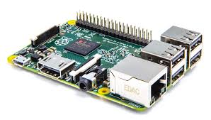
Raspberry Pi 2

Installing LTE modem on Raspberry Pi

I used Sakis3g script to install the drivers and application to configure the LTE modem. You can find more information at http://www.sakis3g.com/

How to communicate with LTE Dongle Private IP

One of the issue with LTE modem (dongle) is that it will be assigned private IP and will use Network Address Translation (NAT) to communicate to external world. NAT is the process where firewall assigns a public address to a network device inside private network. NAT save on the IP addresses as every network device (LTE dongle in our case) does not need a public address, and also it would hide these private devices from the outside world. For our quadcopter LTE dongle, it means that we wont be able to use the IP which is assigned to it in order to establish any IP communication to it. To overcome this problem we have to use our home Wifi router's port forwarding feature (application of NAT). Since our router's public IP is known to us ,therefore forwarding packet to our home PC coming from LTE quadcopter will not be an issue.

Let's assume that LTE dongle is assigned private IP 10.10.10.50 by the LTE network, Let's  also assume our home computer has private of 192.168.10.44 which was assigned by the Wifi router. Secondly our Wifi router has public IP of 173.75.180.60 which is known to us. We use TCP port 50050 for any communication from LTE quadcopter to Home PC. Now all we have to do is defining port forwarding table in our home wifi router. The basic rule that needs to be defined is to forward all incoming TCP packet with destination port of 50050 to our controller PC which has IP 192.168.10.44 and you are all set to have IP communication between Quadcopter and our home PC


Now here is how our end to end Communication will work

- Using Python's socket module function, Raspberry Pi (with LTE modem connected) will open a TCP connection to a port 50050 and IP 173.75.180.60.

- Python Socket Module on our home pc waits until a client connects to the port you specified

- Our home router forwards all incoming TCP packet with destination port of 50050 to our controller PC which has IP 192.168.10.44

- Once a socket is open, you can read from it like any IO object.

Below is the very basic python code that I used to do the communication between Raspberry Pi and home Computer as explained above. The code is just to give you a starting point while you can optimize the code below to have much better stabilized flight :)

Python Code on PC side


Python Code on Raspberry Pi side


Video Streaming from Quadcopter to Home Wifi Network 

Currently I am having trouble transmitting video from Quadcopter to Home Computer. I used  netcat utility to do the streaming but it makes  RPi reset every time. I believe I need to provide separate power bank. I will give update on it once successful, hopefully soon.


LTE Physical Uplink Control Channel (PUCCH)

Physical Uplink Control Channel (PUCCH) carries Uplink Control Information (UCI) which is basically bits and pieces of information that eNB requires from UE in order to understand what UE (user equipment) needs and carries other information like channel quality that UE is seeing in downlink,  etc

UCI is divided into three main sub branches i.e. Channel State Information (CSI), Scheduling Requests (SR) and HARQ ACK/NACK shown with some details as below


Note: 3GPP Release 8 and Release 9 UEs cannot transmit PUCCH and PUSCH on same TTI. If UE has to transmit UCI and data simultaneously within the same TTI, then PUSCH is used for UCI transmission but Release 10 allows simultaneous transmission of PUSCH and PUCCH

3GPP has defined different PUCCH formats to transfer different combinations of the information as can be seen in below table


A single PUCCH transmission always occupies 2 Resource Blocks
Frequency diversity of those two RBs is ensured by slot based PUCCH frequency hopping (See figure below) Each pair of RBs allocated to PUCCH can be used simultaneously by multiple UEs by
using different cyclic shifts and different orthogonal spreading codes


PUCCH Capacity Calculations

Remember every  RRC Connected UE needs to send CQI reports periodically!

Basic formula to calculate how many UEs (RRC Connected) are supported by eNB is

Number of UEs = Number Resource blocks used for CQI reporting x UEs Multiplexed per Resource Blocks x CQI reporting periodicity

The CQI reporting periodicity (in subframes) are determined based on the parameter
cqi-pmi-ConfigIndex given in Table 7.2.2-1A for FDD in 3GPP TS 36.213

Example
Lets assume we have reserved  5 resource blocks (eNB Parameter) for CQI reporting and 6 UEs can be multiplexed per resource blocks. Also lets assume that CQI periodicity is 40 ms then the total number of RRC Connected UEs that eNB can support is as below

Number of UEs= 5 * 6 * 40 = 1200


Note: This is not the only limitation for how many RRC Connected users eNB can support. The above capacity calculation is just to explain the requirement atleast from UE CSI reporting perspective


Connected Mode DRX


We know that 2G and 3G terminal uses discontinuous reception in idle mode. In LTE the tradition has continued and we have similar DRX in idle mode but in addition to that we also have DRX in RRC mode.  In LTE, when there is no data to receive or transmit in RRC connected mode, UE would switch off its transceiver for a very short interval. It will start similar "wake up and sleep " cycle. During the wake up period, it will keep monitoring PDCCH channel for UL or DL grants whereas the sleep periods will improve the battery savings

Without Connected Mode DRX 

The main goal of Connected mode DRX is to minimize battery consumption by discontinuous monitoring of PDCCH channel. Without DRX, UE has to monitor PDCCH channel every time. This results in high battery consumption as shown below


With Connected Mode DRX

With DRX enabled in connected mode, UE only monitors PDCCH channel when it is awake during the sleep/wakeup cycles as seen below. During the sleep time, UE doesn't monitor PDCCH channels which results in energy savings. All the DL grants are delayed to nearest wake up period


Important DRX Parameters/Timers 

Some of the important parameters used in configuring the DRX for UE are shown below. The parameters are transferred to UE through RRC reconfiguration message


Basic Scenario

To better understand these parameters, see the below picture which shows each parameter

  1.  UE is in RRC Connected mode and is continuously monitoring PDCCH. At this point, there is DL Grant and downlink data. The DRX inactivity timer and the main RRC Inactivity timer are restarted
  2. There is UL grant for UE. With DL Grant both DRX and RRC inactivity timers are restarted. 4 ms later UE sends data in uplink
  3. The DRX Inactivity timer is expired since there were no further grants in uplink or downlink. Though UE was constantly monitoring PDCCH. UE now enters the short DRX cycle. The battery savings have just started
  4.  The DRX short cycle timer got expired therefore UE will end up its short DRX cycle and enter the long DRX cycle
  5. The main RRC inactivity timer got expired since there was no activity in uplink or downlink for the duration for RRC Inactivity timer. The UE will go to RRC IDLE state. In idle state UE will use paging DRX cycle


HARQ Retransmissions Scenario

In the above basic scenario it may seem complicated to include HARQ retransmission's scenarios, so here is another example below
  1.  UE is in RRC Connected mode and is continuously monitoring PDCCH channel. At this point, there is DL Grant and downlink data. The DRX and RRC inactivity timer is restarted ( RRC Inactivity not shown here)
  2. There is UL grant for UE. With DL Grant both DRX and RRC inactivity timers are restarted 4ms later UE sends data in uplink. And after additional 4ms later ACK is sent by eNB
  3. There is DL grant for UE with DL data. For some reason UE is not able to decode the data. 4ms later UE will send NACK towards eNB. Harq RTT timer is started which has fixed duration of 8ms. Now UE is expecting retransmission in downlink
  4. HARQ RTT got expired which will trigger the DRX retransmission timer as the retransmission is expected
  5. There is DL grant with retransmission data. This time UE is able to decode it. 4ms later UE sends ACK in uplink. Note DL grant for retransmission data does not restart DRX inactivity timer
  6. DRX retransmission timer expires and UE enters the short DRX cycle


Key points:
  •  DRX cycles are synchronized at UE and eNB side i.e. eNB knows when UE is in DRX sleep or awake period so that it can schedule UE accordingly
  • When UE is in DRX sleep state, it cannot read PDCCH channel therefore, the downlink grants must be delayed to nearest wake cycle as eNB is already aware of this UE DRX cycle. The introduces delay in dowlink transmission
  • Uplink transmission is not affected as UE can send SR in uplink whenever it wants i.e. UE is in DRX sleep period and it has uplink data so it will just wake up and send SR to receive UL grants from eNB. 
  • Other than the timers/parameters mentioned above, eNB MAC can also control UE DRX by transmitting MAC CE DRX commands


LTE in Unlicensed Spectrum (LTE-U)

LTE in Unlicensed spectrum (LTE-U) is one of the hot topics in 2015 telecom industry. LTE-U extends the benefits of LTE and LTE Advanced to unlicensed spectrum, enabling mobile operators to offload data traffic onto unlicensed frequencies more efficiently.

LTE-U also poses major challenges to WiFi as both will operate in an unlicensed and un-controlled spectrum. However, various techniques have been developed to share the unlicensed spectrum fairly between LTE and WiFi technologies. Please check below white paper from Nokia for more details on LTE-U

RSRP, RSSI and RSRQ

In LTE network, UEs need to measure signal strength of its own and neighbor cells constantly, during idle, connected mode or handovers in order to keep the signal quality constant. UE measures RSRP and RSRQ in LTE

Reference Symbol Received Power (RSRP):

  • RSRP is the linear average of the downlink reference signals across the channel bandwidth 
  • RSRP provides information about signal strength and  gives no indication of signal quality 
  • RSRP measurements are used in handover, cell selection and cell re-selections 
  • The reporting range of RSRP is defined from -140 dBm to -44 dBm with 1 dB resolution as shown in table below
RSRP measurement report mapping (3GPP Reference: TS 36.133)

Received Signal Strength Indicator (RSSI):

  • RSSI represents the total received wide-band power by UE
  • RSSI is measured only in symbols containing Reference signals 
  • RSSI includes power from serving cell as well as co-channel interference and noise
  • RSSI helps in determining interference and noise information 
  • RSSI is never reported by UE

Reference Signal Received Quality (RSRQ):

  • RSRQ indicates quality of received reference signal. RSRQ measurement and calculation is based on RSRP and RSSI since RSRP determines signal quality and RSSI determines co-channel interference and noise. RSRQ formula is shown below (N represents number of resource blocks)
  • The reporting range of RSRQ is defined from -19.5 dB to -3 with 0.5 dB resolution
RSRQ measurement report mapping (3GPP Reference: TS 36.133)

Example

Lets try to calculate RSRP, RSSI and RSRQ for one very simple case of one resource block with 12 sub carriers and 0.5 ms in time domain. For sake of simplicity, lets assume the power of reference symbols  (shown by red square) and power of other symbols carrying other data channels (shown by blue square) is same i.e. 0.021 watt


Since RSRP is linear average of downlink reference signal for given channel bandwidth therefore
RSRP = 10*log (0.021*1000) = 13.2 dBm

While RSSI is total received wide-band power. Therefore we have to add power of all 12 carriers in the given resource block
RSSI = 10*log(0.021*1000)+10*log(12) = 24 dBm

RSRQ is now simple ratio of RSRP to RSSI with N=1
RSRQ = 10*log(0.021/(12*0.021)) = -10.79 dB


Why do we use dBm as a unit of Power

We use decibels-milliwatts to measures power levels in telecommunication and other fields instead of Watt. The reason to use logarithmic scale is that it helps in reducing massive values to smaller number

Example : 0.00000000000080 watt which apparently looks very small value but
can still be received by antenna. The logarithmic value is just -91 dbm by using below formula
P (dBm) = 10 x Log (1000*P)

dBm vs dB

dB is ratio between two power values while dBm is used to express an absolute value of power. So when we mention RSRP and RSSI we shall always use dBm since we are talking about absolute power values but we need to use dB with RSRQ since it is the ratio of RSRP to RSSI