Transport Block Size, Throughput and Code rate

Since the size of transport block is not fixed, often a question comes to mind as to how transport block size is calculated in LTE.

Back Ground
If we only consider "Uplink direction" and we assume that the UE is already attached to the network, then data is first received by PDCP (Packet data compression protocol) layer. This layer performs compression and ciphering / integrity if applicable. This layer will pass on the data to the next layer i.e. RLC Layer which will concatenate it to one RLC PDU.

RLC layer will concatenate or segment the data coming from PDCP layer into correct block size and forward it to the MAC layer with its own header. Now MAC layer selects the modulation and coding scheme configures the physical layer. The data is now in the shape of transport block size and needed to be transmitted in 1ms subframe.
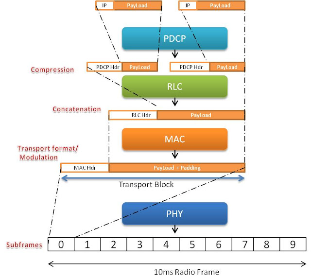



Transport Block size

Now how much bits are transferred in this 1ms transport block size? 
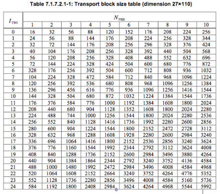
It depends on the MCS (modulation and coding scheme) and the number of resource blocks assigned to the UE. We have to refer to the Table 7.1.7.1-1 and Table 7.1.7.2.1-1 from 3GPP 36.213

Lets assume that eNB assigns MCS index 20 and 2 resource blocks (RBs) on the basis of CQI and other information for downlink transmission on PDSCH. Now the value of TBS index is 18 as seen in Table 7.1.7.1-1


After knowing the value of TBS index we need to refer to the Table 7.1.7.2.1-1 to find the accurate size of transport block (Only portion of the table is shown here while for the complete range of values refer to 3gpp document 36.213 http://www.quintillion.co.jp/3GPP/Specs/36213-920.pdf)


Now from the Table 7.1.7.2.1-1 the value of Transport block size is 776 bits for ITBS = 18 and NPRB=2

Throughput

Throughput is simply = Transport block size*(1000) = 776 *1000 = 776000 bits / seconds = 0.77 mbps (Assuming MIMO not used)

Please check this Throughput Calculator which takes MCS values and number of resource blocks as input to calculate the downlink throughput


Code Rate

In simple words, code rate can be defined as how effectively data can be transmitted in 1ms transport block or in other words, it is the ratio of actual amount of bits transmitted to the maximum amount of bits that could be transmitted in one transport block

code rate = (TBS + CRC) / (RE x Bits per RE)

where
TBS = Transport block size as we calculated from Table 7.1.7.2.1-1
CRC = Cyclic redundancy check i.e. Number of bits appended for error detection
RE = Resource elements assigned to PDSCH or PUSCH
Bits per RE = Modulation scheme used


While we know the values of TBS, CRC and bits per RE (modulation order), it is not easy to calculate the exact amount of RE used for PDSCH or PUSCH since some of the REs are also used by control channels like PDCCH, PHICH etc

In our case, lets assume that 10% of RE's are assigned for control channels then

TBS = 776
CRC = 24
RE = 2 (RB) x 12 (subcarriers) x 7 (assuming 7 ofdm symbols) x 2 (slots per subframe) x 0.9 (10% assumption as above) = 302 REs
Bits per RE = 6 (Modulation order from table 7.1.7.1-1)

So

code rate = (776 + 24) / (302 * 6 ) = 0.4


AKA Digest authentication scheme for VoLTE (IMS)

When a VoLTE client needs to connect to IMS network, it has to authenticate the network while network also needs to make sure that only the correct user is registered to its network. AKA Digest is one of the scheme to authenticate VoLTE client to the IMS server


AKA

AKA stands for "Authentication and key agreement". This scheme comes from the legacy 3gpp networks and has been widely used in LTE, 3G, CDMA and WiMAX technologies. In this mechanism, a secret key is already known to both user device (USIM, iSIM) and authentication servers (HSS, HLR). 

The server will challenge the end user using AKA algorithms and shared key and sends RAND, AUTN values towards UE. UE will authenticate network and prepares result (RES for network to authenticate UE) with the help of shared key in UICC and parameters sent by Server.


HTTP Digest

Http Digest is the popular authentication scheme used for authenticating users to access web servers and other applications which requires security and data integrity. This scheme is much secure than the basic authentication as it applies hash function to the password before sending it [RFC2617]. 

HTTP Digest is username / password based authentication procedure. The authentication server provides one time created " nonce " value to the client. The client uses the nonce value and creates a secure response that contains  the password, username and other parameters to the server. The password which is known both to server and client, is always fixed


Now For IMS

Now since IMS is a part of 3GPP and on the contrary SIP signaling defines http digest for authentication [RFC3261]. Therefore in order to use 3GPP AKA with IMS, the parameters from AKA are mapped onto http digest [RFC3310]. In simple words the parameters / headers used to transport http digest information, will transport AKA information in identical format

With 3GPP AKA digest, the "nonce" now contains RAND, AUTN. The password now contains the one time RESPONSE generated by client with help of UICC (USIM, ISIM). Thus the method is even more secure. 


Authentication in IMS networks

  • VoLTE Client sends SIP register request to IMS Server. The user is not authenticated at this  point. The SIP register request contains IMS related identities (private identity, public identity, URI, etc)
  • The IMS server (S-CSCF) obtains authentication vector and SQN from HSS that contains a random challenge RAND, authentication token AUTN, expected authentication result XRES, a session key for integrity check IK, and a session key for encryption CK
  • The server creates an authentication request, which contains the random challenge RAND, and the network authenticator token AUTN
  • The authentication request is delivered to the client with "401 UNAUTHORIZED" message
  • The client verifies the AUTN with the ISIM. If the verification is successful, the network has been authenticated. The client then produces an authentication response RES, using the shared secret K and the random challenge RAND
3GPP AKA Operation in IMS


  • The authentication response RES is delivered to the server using new regiser sip message
  • The server compares the authentication response RES with the expected response. If the two match, the user has been successfully authenticated
  • Session keys IK and CK can be used for protecting further communications between the client and the server
  • Server sends "200 OK" message to inform the VoLTE client about successful registration


Android Operating System and Radio Interface Layer

When the mobile phone is switched on, in the first step Linux Kernel is loaded along with the drivers for modem and the first process called "init" is started. 'Init' will start initial dummy process named 'zygote' which helps in starting other services like audio manager, surface flinger, power manager, RIL Daemon (to be explained later), service manager, Telephony service etc 

All the smartphone applications communicate to external ports or environment via Application programming interface (API). For communication towards radio modem, Telephony framework (mentioned above) performs the role of APIs. It helps to access network related services by applications i.e. PDP connection establishment, SMS, MMS etc. Whenever these applications make any query, it is forwarded to Radio interface Layer (RIL) by telephony framework APIs. RIL is interface between telephony framework and radio hardware (modem)

RIL has two sub layers 

  • RIL Daemon: It communicates with Vendor RIL for call processing and other functions
  • Vendor RIL: It contains Library of functions and drivers to particular modem. It communicates with the radio hardware 


RIL Daemon is responsible for initializing Vendor RIL and forwards all requests from telephony framework to Vendor RIL. Vendor RIL communicates to modem protocol stacks via Hayes AT commands and forwards requests from modem to RIL Daemon or vice versa. Please see the figure above.

So here it is what happens:

  1. Android Mobile is switched on
  2. Linux Kernel is loaded
  3. Initial temporary process named zygote is started on initialization by Linux Kernel
  4. Zygote helps in quick start of other services including Android Telephony network and RIL Daemon (RILD)
  5. RILD initializes the vendor RIL for communication
  6. Vendor RIL initiates the radio modem
  7. Network attach procedure is started


System Information Block 1

After initial cell synchronisation and reading Master information block, UE will proceed to read system information blocks to obtain important cell access related parameters.

SIB1 broadcasts common information to all UEs in the cell related to cell access parameters and information related to scheduling of other SIBs. SIB1 is broadcasted in subframe # 5 in the SFN for which SFN mod 8 = 0. While the repeated copies are sent in subframe # 5 for which SFN mod 2 = 0 . Thus the new copy of SIB1 is transmitted every 80ms as shown below


The cell access related parameters are listed below

  • PLMN identity : Upto 6 PLMN identies can be specified
  • Tracking area code: Range from 0 to 65546
  • Cell Id: It contains eNB identity and has length of 28 bits
  • Cell barred: whether cell is barred or not
  • Intra Frequency cell reselection info: To select other cells when the target cell is barred
  • CSG indication: To indicate whether this cell is CSG cell or not. If it is CSG cell, then CSG identity stored in the UE should match with CSG id of the cell
Other information broadcasted by SIB 1 are 
  • q-RxLevMin: Minimum required level in the cell 
  • Band indicator: Cell frequency band indicator
  • scheduling information of other system information blocks
Complete SIB1 info is shown below (taken from UE logs). This SIB1 does not represent any real network